Projection system, control device, and control method of projection system

a technology of projection system and control device, which is applied in the direction of television system, selective content distribution, instruments, etc., can solve the problems of complex configuration of each projector, large installation state, and unsightly installation state, and achieve the effect of simple connection configuration

Active Publication Date: 2018-03-22
SEIKO EPSON CORP
View PDF2 Cites 8 Cited by
  • Summary
  • Abstract
  • Description
  • Claims
  • Application Information

AI Technical Summary

Benefits of technology

[0006]An advantage of some aspects of the invention is to realize a simple connectio

Problems solved by technology

For this reason, a configuration of each of the projectors becomes complicated and becomes large.
In addition, since t

Method used


Image

  • Projection system, control device, and control method of projection system
  • Projection system, control device, and control method of projection system
  • Projection system, control device, and control method of projection system

Examples


Embodiment Construction

[0038]Hereinafter, an embodiment of the invention will be described with reference to accompanying drawings.

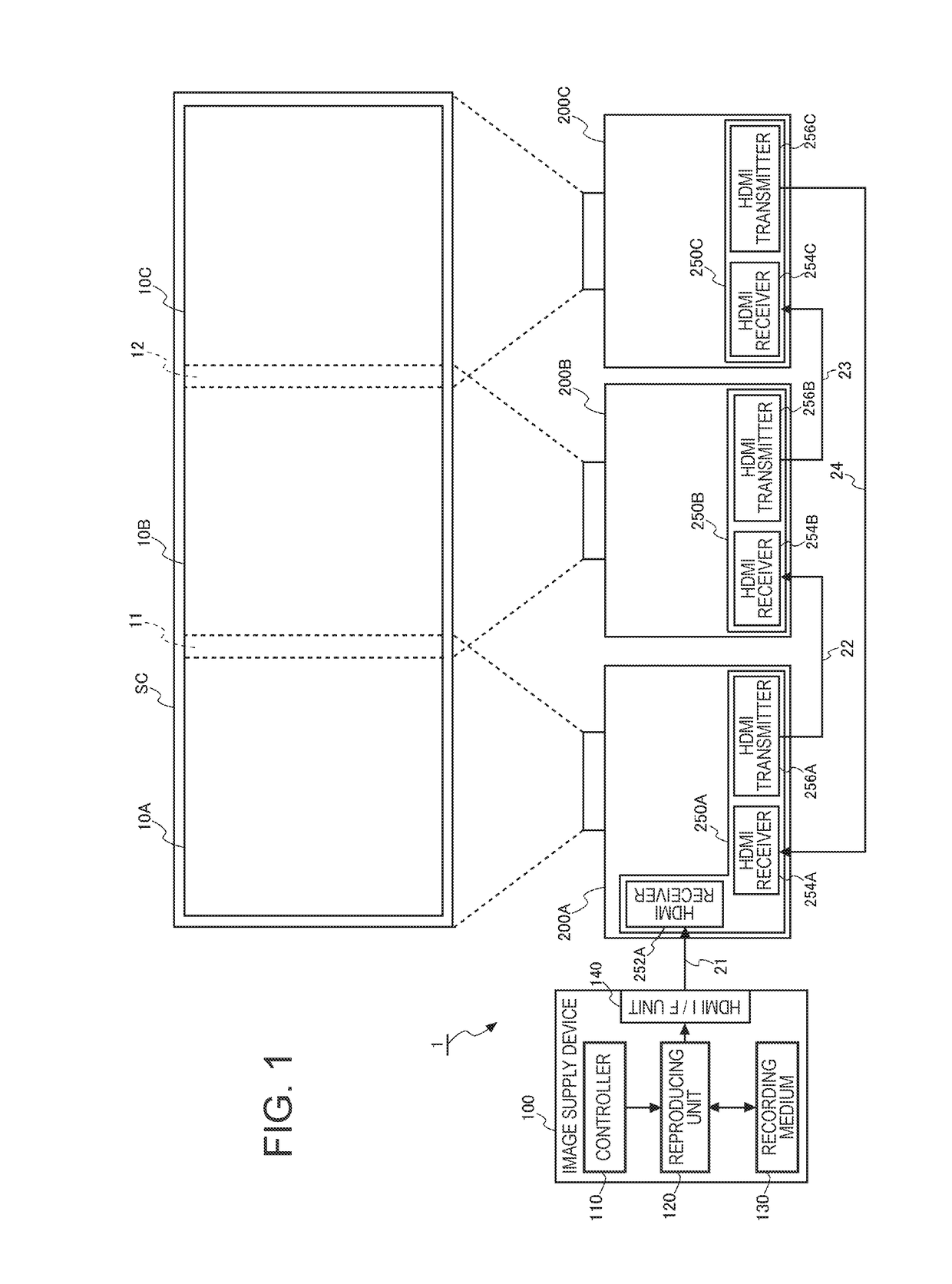
[0039]FIG. 1 is a system configuration diagram of the embodiment to which the invention is applied.

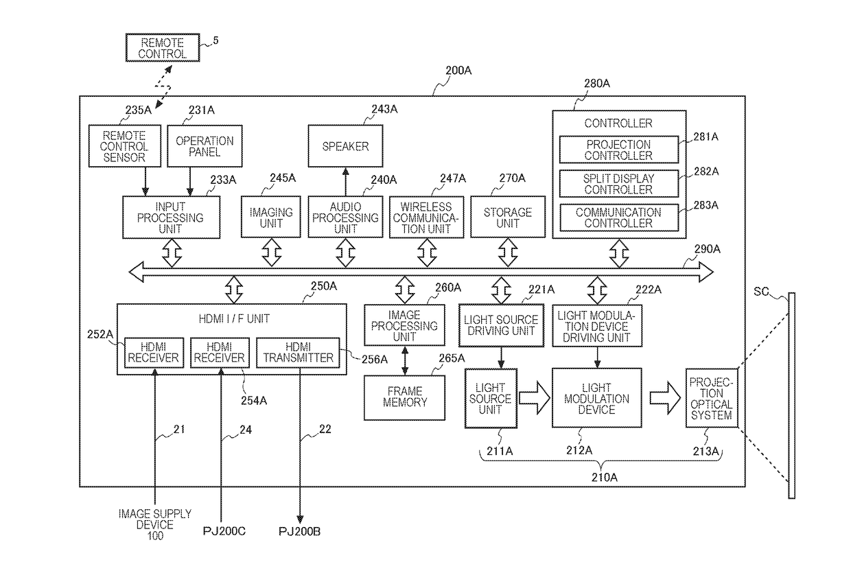
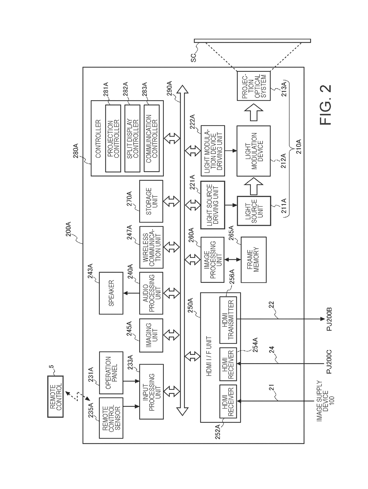
[0040]A projection system 1 of the present embodiment includes an image supply device 100 and a plurality of projectors 200. In FIG. 1, three the projectors 200 of projectors 200A, 200B, and 200C are illustrated as the plurality of projectors 200, but the number of the projectors 200 is not limited to three. The projection system 1 may include at least one projector 200 as a master machine and one projector 200 as a slave machine. A master machine and a slave machine will be described below.

[0041]The image supply device 100 is connected to the projector 200 operating as a master machine and supplies an HDMI (registered trademark) signal to the projector 200 of a master machine. In the HDMI signal, at least image data is included and audio data may be included in addition to the i...


PUM


Abstract

A projector system includes a plurality of projectors, in which a projector A and a projector B, and the projector B and a projector C are connected by a daisy chain method via each of cables, and the projector A outputs control information which controls the projector B or the projector C to the projector B via a data line of the cable along with image data and the projector B extracts and processes the control information input from the data line of the cable.

Description

CROSS-REFERENCE[0001]The entire disclosure of Japanese Patent Application No. 2016-183711, filed Sep. 21, 2016 is expressly incorporated by reference herein.BACKGROUND1. Technical Field[0002]The present invention relates to a projection system, a control device, and a control method of a projection system.2. Related Art[0003]In the related art, a projection system in which a plurality of projectors are connected by a cable and an image is projected by the connected plurality of projectors is known (see, for example, JP-A-2008-216805).[0004]JP-A-2008-216805 discloses an image projection system in which a plurality of projectors are connected by a so-called daisy chain method by a cable for image transmission and a cable for command transmission.[0005]However, in the image projection system of JP-A-2008-216805, since the plurality of projectors are connected to each other using a plurality of cables, each of the projectors must have a plurality of interfaces for cable connection. For ...

Claims


Application Information

Patent Timeline
IPC IPC(8): H04N9/31H04N21/4363H04N21/41G06F3/14
CPCH04N9/3147H04N21/43635H04N21/4122H04N9/3155G06F3/1446H04N5/765H04N9/3141G09G5/006G09G5/12G09G2350/00G09G2356/00G09G2370/022G09G2370/12G03B21/13G03B21/14G03B21/00G03B21/2013
Inventor YAMAMOTO, TAKEKUNINAGUMO, TAKASHI
Owner SEIKO EPSON CORP
Why Eureka
Try Eureka