An Aircraft for Aerial Delivery

a technology for aircraft and airframes, applied in the field of aircraft, can solve the problems of increasing increasing increasing the difficulty of users, so as to reduce the complexity of aircraft design, reduce the cost of airframes and control modules, and facilitate the effect of user

Inactive Publication Date: 2018-03-29
COOL GEORGE MICHAEL
View PDF7 Cites 7 Cited by
  • Summary
  • Abstract
  • Description
  • Claims
  • Application Information

AI Technical Summary

Benefits of technology

[0044]In an embodiment, the aircraft is a glider. Thus, the aircraft does not require an on-board means of providing propulsion. In some embodiments, the aircraft may have a glide ratio of 3:1, 5:1 or preferably 10:1. That is to say, for every 10 units of distance the glider travels, the glider descends by 1 unit of distance. Embodiments thus provide a delivery system in which a low-cost aircraft can be produced. There is no requirement for potentially expensive propulsion systems, and both the cost of the airframe and the control module can be reduced. The use of a glider also reduces the complexity of the design of the aircraft and therefore makes it easier for a user at the target location to disassemble the aircraft after delivery (i.e. remove the control module). Further advantages include lower potential environmental impact as fuel or large batteries are not required to power the device. Furthermore, the equipment required to control the aircraft may be simpler, since there is no need to control the propulsion means.
[0045]In another embodiment, the airframe comprises a hold for receiving the load to be delivered. The hold may comprise a separate compartment in the main body for receiving the load, so as to avoid interference with the linkages by the goods and/or to protect the load from damage.
[0046]In another embodiment, the main body comprises at least one recessed portion adapted to at least partially receive the at least one deployable wing in the stowed configuration. Use of a recess or cavity to store the wing(s) in the stowed configuration can reduce the risk of damage to the wing(s), for example when loading and moving the aircraft. This can also reduce the footprint of the aircraft in its collapsed configuration and increase the stacking efficiency of the aircraft, for example by providing a substa

Problems solved by technology

While many systems for delivery of goods have been developed, many, however, have numerous limitations.
Often the intended delivery site is either in a very remote location or in a hostile region, which means that delivery by land, for example via a convoy of vehicles, can be slow and/or dangerous.
Furthermore, delivery by land is not always a viable option in regions where the terrain is impassable.
The alternative, delivery by air, is an expensive method of delivering goods and requires either a suitable landing zone for an aircraft or requires the use of aerial delivery systems, such as air drops, to delivery goods.
These limit the sites to which goods can be delivered and the aerial delivery methods are not always accurate.
In some hostile regions, even aerial delivery is too dangerous, as the risk to life and the aircraft is too high.
This is often costly and time consuming, as it will require flying to each site and landing/unloading.

Method used


Image

  • An Aircraft for Aerial Delivery
  • An Aircraft for Aerial Delivery
  • An Aircraft for Aerial Delivery

Examples


first embodiment

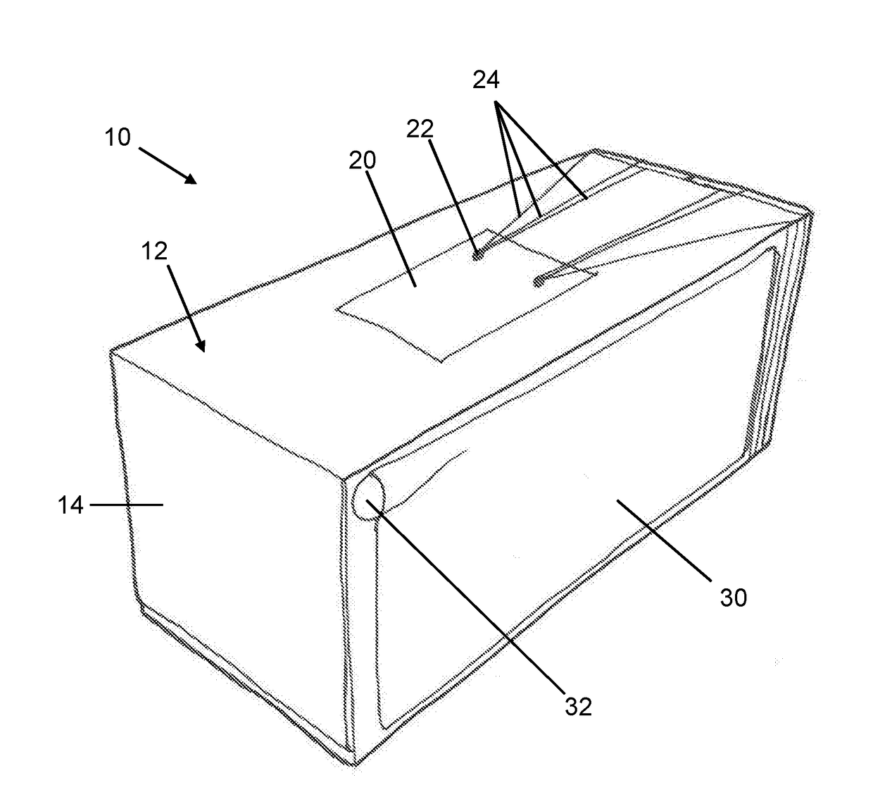
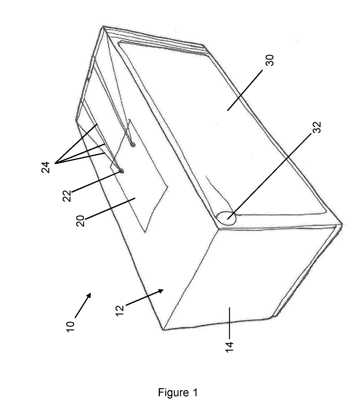
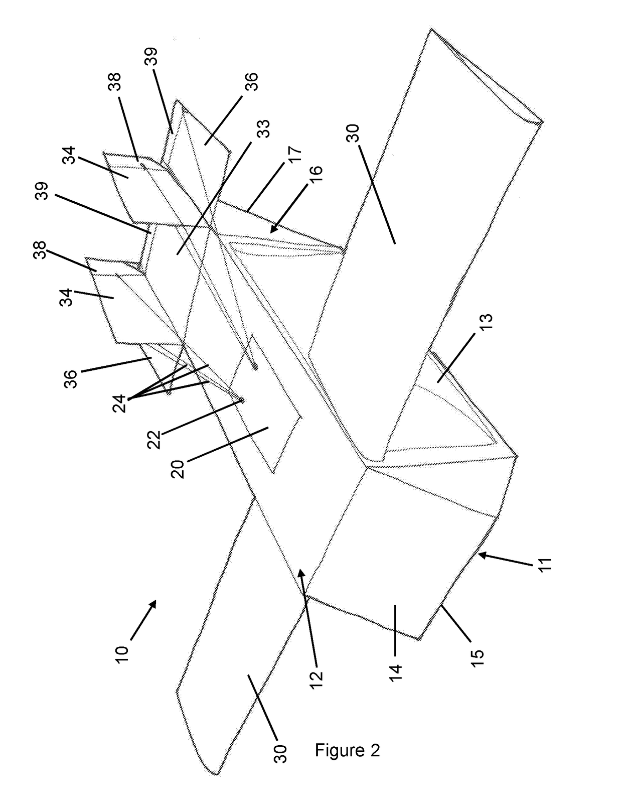
[0066]the invention is shown in FIGS. 1 and 2 in the form of a glider 10. FIGS. 1 and 2 depict the glider 10 in a collapsed (or stowed) configuration and a deployed configuration, respectively. The glider 10 acts as a means by which goods can be delivered to a target located easily and at a low cost, as will be explained below. The glider 10 is initially stored in the collapsed configuration shown in FIG. 1 so that it can be efficiently packed, or stacked together with other such gliders, for example. The size of the glider in the collapsed configuration shown in FIG. 1 is approximately 500 mm×500 mm×1200 mm. When the glider is launched, it automatically deploys (as will be discussed in detail, below) into the deployed configuration shown in FIG. 2 thus providing all of the required components to allow the efficient aerial delivery of the goods stored within the glider 10.

[0067]In this embodiment, the glider 10 comprises an airframe, the airframe being formed from corrugated cardboa...

third embodiment

[0107]the invention is shown in FIGS. 6 and 7. The aircraft 210 of this embodiment has a similar basic structure to the previous embodiments in that it comprises a main body 212, wings 230a, 230b, a tail section 216, a hold for goods (not visible), a control module and linkages. The main differences between this aircraft 210 and the gliders 10, 110 of the previous embodiments are the provision of propulsion means in the form of a deployable propeller 211, an internally mounted control module (not visible), internally mounted linkages (not visible) and the wing 230a, 230b structure.

[0108]The control module in this embodiment is housed within the main body 212 of the airframe so that it is not visible in normal use. It can be inserted into and removed from the main body via an access panel (not visible). Linkages extend from the control module to the control surfaces and the wing deployment mechanisms internally, within the airframe. This reduces the risk of a linkage becoming snagged...


PUM


Abstract

An aircraft for the autonomous aerial delivery of a load to a target location, the aircraft comprising an airframe having at least one adjustable control structure for controlling the flight of the aircraft and a main body adapted to receive a load a self-contained control module releaseably connected to the airframe, the control module containing an actuator for adjusting the control structure and a controller for producing an electrical drive signal for controlling the actuator; and at least one linkage extending from the control module to the at least one adjustable control structure so as to operably connect the control module to the at least one adjustable control structure, wherein the actuator of the control module is adapted to adjust the at least one adjustable control structure using the at least one linkage so as to control the flight of the aircraft and to steer the aircraft to the target location.

Description

FIELD OF INVENTION[0001]The present invention relates to an aircraft, in particular an aircraft for the autonomous aerial delivery of a load to a target location.BACKGROUND TO THE INVENTION[0002]Logistics is a fundamental part of any operation, whether humanitarian, commercial or military and vast sums of money are spent building infrastructure and delivering goods to remote or hard-to-reach locations. While many systems for delivery of goods have been developed, many, however, have numerous limitations.[0003]Often the intended delivery site is either in a very remote location or in a hostile region, which means that delivery by land, for example via a convoy of vehicles, can be slow and / or dangerous. Furthermore, delivery by land is not always a viable option in regions where the terrain is impassable. The alternative, delivery by air, is an expensive method of delivering goods and requires either a suitable landing zone for an aircraft or requires the use of aerial delivery system...

Claims


Application Information

Patent Timeline
IPC IPC(8): B64C13/28B64C3/56B64C1/06B64C31/02B64C39/02
CPCB64C13/28B64C3/56B64C1/061B64C31/02B64C39/024B64C2001/0054B64C2201/128B64C2201/141B64C2211/00B64U30/12B64U2101/60B64C13/30Y02T50/40B64U10/25B64U2201/10
Inventor COOK, GEORGE MICHAELCOOK, JONATHAN EDWARDCOOK, MICHAEL KEVIN
Owner COOL GEORGE MICHAEL
Why Eureka
Try Eureka