Supercharge Your Innovation With Domain-Expert AI Agents!

Self-winding watch

a self-winding, watch technology, applied in the direction of electric winding, instruments, horology, etc., can solve the problems of high torque required for winding the spring, and high gear ratio, so as to preserve the function of the oscillating weight when worn, reduce the torque, and keep the effect of operation

Active Publication Date: 2018-03-29
THE SWATCH GRP RES & DEVELONMENT LTD
View PDF0 Cites 1 Cited by
  • Summary
  • Abstract
  • Description
  • Claims
  • Application Information

AI Technical Summary

Benefits of technology

The invention is a self-winding device that reduces the torque required to wind the barrel spring. It also allows the watch to be wound when not worn and keeps it in operation, even when the oscillating weight is worn. The device is easy to install and can replace the existing movement without major changes.

Problems solved by technology

Generally, the oscillating weight is mounted to be rotatably guided on a shaft with an unbalance.
However, the torque required for winding the spring is quite high and this involves a powerful, and therefore bulkier, motor or an also cumbersome high gear ratio.

Method used


Image

  • Self-winding watch
  • Self-winding watch

Examples


first embodiment

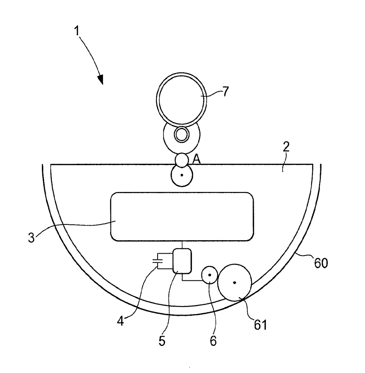
[0037] the drive means 6 comprise a brushless-type micromotor or a Lavet type stepping motor well known in the clockmaking industry, or an axial flux motor, for example, or also a piezoelectric type motor, and the micromotor comprises a transmission shaft, at the end of which a pinion 61 is mounted, which is arranged to cooperate with a toothed ring 60, or also a toothed sector formed in the watch or assembled on the latter. In this way, when the micromotor is active, it displaces the oscillating weight 2 around the axis A, which has the effect of winding the barrel spring through a reduction wheel train 7 commonly used in self-winding mechanical watches. The advantage of such a solution is that a much less significant torque is required than in known devices because of the reduction that the wheel train 7 provides.

second embodiment

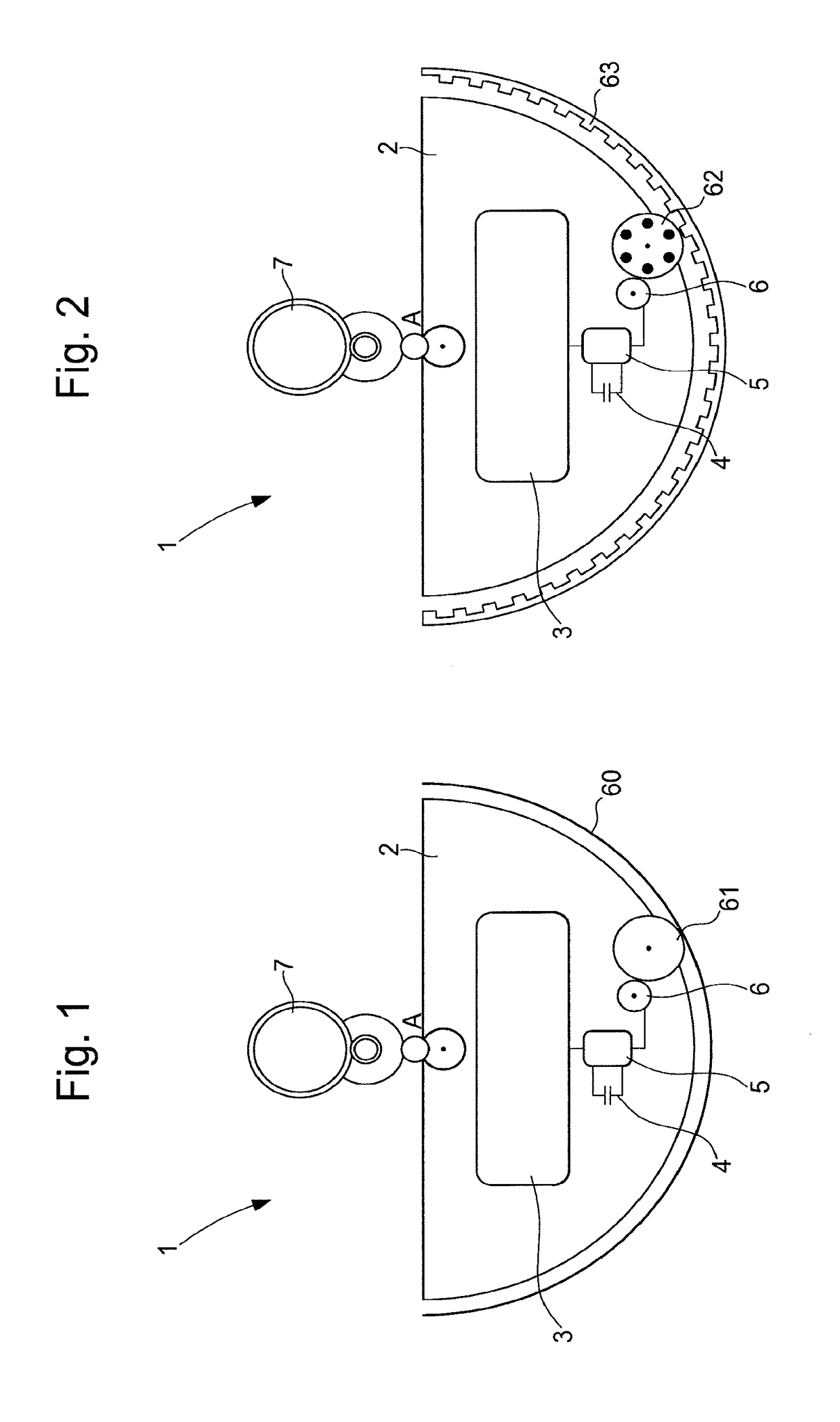
[0038] shown in FIG. 2 the drive means 6 comprise a magnetic coupling between a wheel 62 composed of magnets or a magnet in one piece driven by the micromotor and a ferromagnetic notched wheel 63 integral to the watch, wherein the magnets of the wheel 62 are attracted by the notches of the notched wheel 63, and this drives the oscillating weight 2 without there being any contact.

[0039]The force of the magnetic coupling is selected so as to drive the oscillating weight 2 up to a certain torque lower than the maximum torque of the barrel spring. This prevents stressing of the spring and allows the oscillating weight 2 to do its winding work while worn. Moreover, the absence of contact means significant stresses can be avoided on the teeth of the gears in the event of impact because of the high inertia of the oscillating weight 2.

[0040]Supposing that the photovoltaic cell 3 is illuminated and the electrical energy storage unit 4 is initially discharged, the current supplied by the phot...


PUM


Abstract

The invention relates to a self-winding watch comprising a movement connected to a winding device of a barrel spring comprising an oscillating weight pivoting around an axis A, a reduction wheel train cooperating with the oscillating weight to transmit the torque to the barrel, a storage unit for electrical energy, a photovoltaic cell arranged to receive the ambient light and charge the electrical energy storage unit, a control circuit connected to the terminals of said electrical energy storage unit and drive means connected to the circuit and coupled to the oscillating weight to displace it. According to the invention the electrical energy storage unit, the control circuit and the drive means are integrated to the oscillating weight.

Description

[0001]This application claims priority from European Patent Application No. 16190915.5 filed on Sep. 27, 2016, the entire disclosure of which is hereby incorporated herein by reference.FIELD OF THE INVENTION[0002]The present invention relates to the technical field of self-winding devices. More specifically, the invention relates to a device that enables a barrel spring of a timepiece, for example, to be wound by means of ambient light energy by a photovoltaic cell.BACKGROUND OF THE INVENTION[0003]Watch movements require drive means to supply energy to an assembly of mechanisms that serve to give at least one time indication.[0004]In the case of mechanical watches this is a mainspring or barrel spring, which is wound by the action of a manually operated winding mechanism or as a result of the movements of the wearer that are transmitted to the barrel spring via an oscillating weight connected to a reduction wheel train. The invention relates to self-winding clockmaking movements usi...

Claims


Application Information

Patent Timeline
Patent Type & Authority Applications(United States)
IPC IPC(8): G04C10/02G04B5/08
CPCG04C10/02G04B5/16G04B5/08G04B5/02G04C1/00G04C1/062
Inventor TOMBEZ, LIONELBORN, JEAN-JACQUESWILLEMIN, MICHELWINKLER, PASCALPARATTE, LIONEL
Owner THE SWATCH GRP RES & DEVELONMENT LTD
Features
  • R&D
  • Intellectual Property
  • Life Sciences
  • Materials
  • Tech Scout
  • Unparalleled Data Quality
  • Higher Quality Content
  • 60% Fewer Hallucinations
Learn More