Location estimation system, location estimation method, and base station control device

a technology of location estimation and location estimation, which is applied in the direction of location information based services, measurement devices, instruments, etc., can solve the problems of difficult to calculate the precise distance between the wireless communication terminal and the base station device, and achieve the effect of improving the accuracy of location estimation

Active Publication Date: 2018-03-29
PANASONIC INTELLECTUAL PROPERTY CORP OF AMERICA
View PDF0 Cites 14 Cited by
  • Summary
  • Abstract
  • Description
  • Claims
  • Application Information

AI Technical Summary

Benefits of technology

[0009]The embodiments in this disclosure enables the improvement of the accuracy of location estimation of a wireless communication terminal in a millimeter wave wireless communication network.

Problems solved by technology

However, the beam pattern of each base station device is unknown to the wireless communication terminal, and therefore, it is difficult to calculate a precise distance between the wireless communication terminal and the base station device based on the intensity of received signal as in the location detection method disclosed in Japanese Patent No. 3,829,784.
As a result, it is difficult to perform a location estimation of the wireless communication terminal with a high degree of accuracy.

Method used


Image

  • Location estimation system, location estimation method, and base station control device
  • Location estimation system, location estimation method, and base station control device
  • Location estimation system, location estimation method, and base station control device

Examples


embodiments

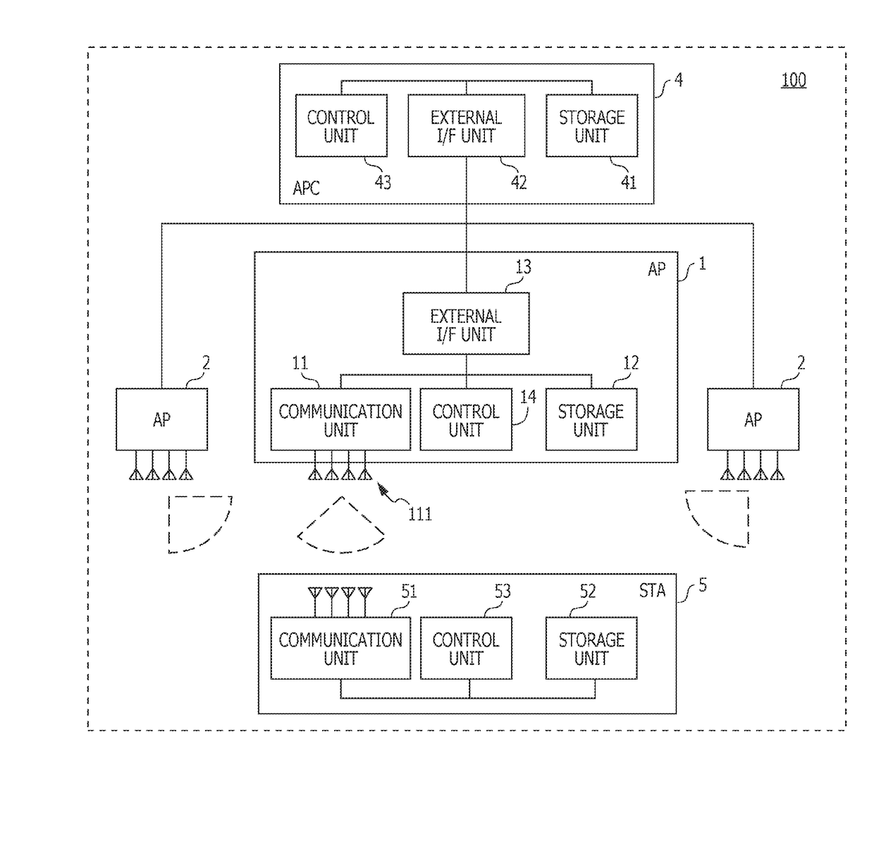
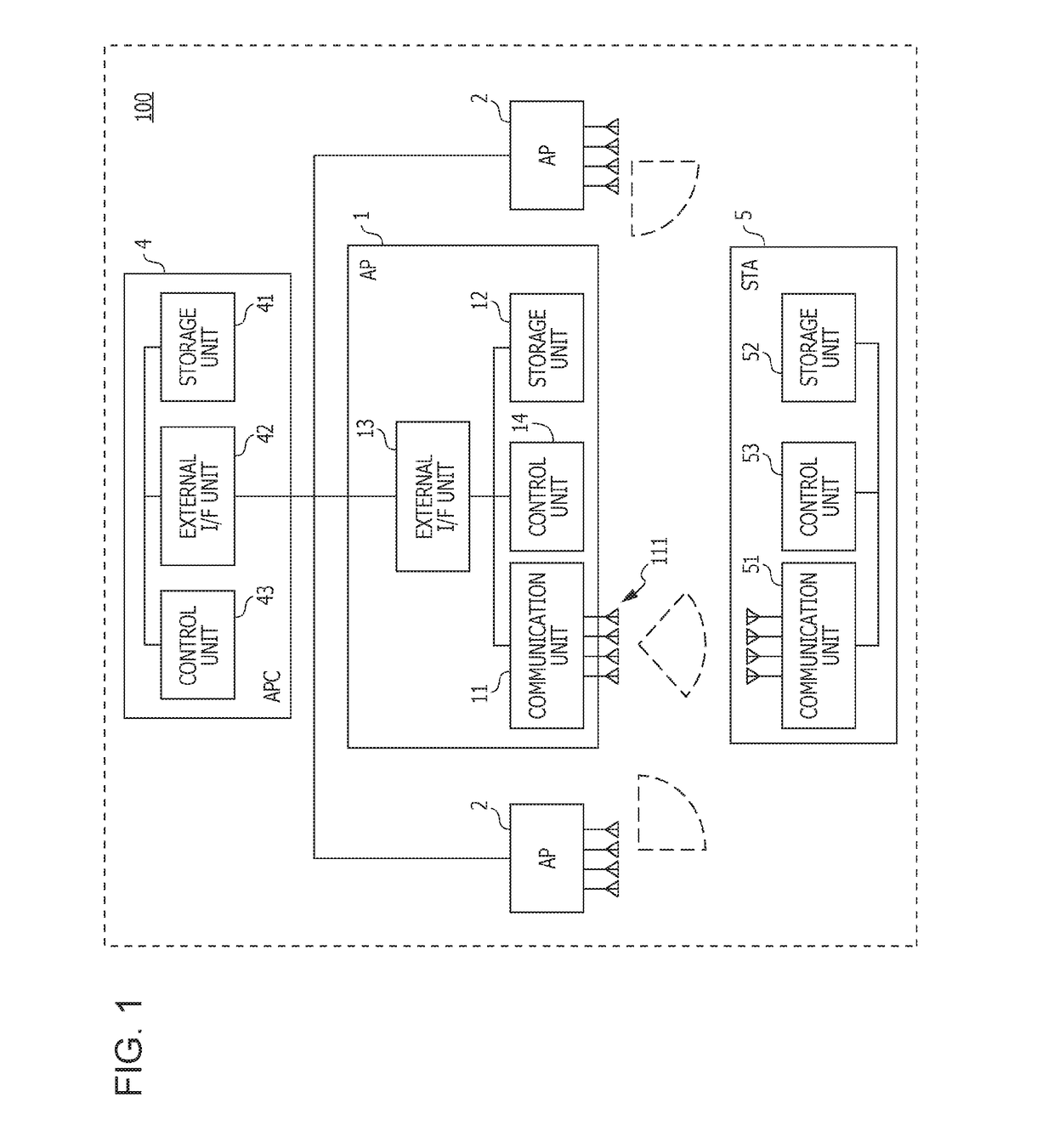
[0017]FIG. 1 is a diagram illustrating an example of system configuration of a millimeter wave wireless communication system 100 according to the present embodiment. The millimeter wave wireless communication system 100 of FIG. 1 includes an access point (AP) 1, an AP 2, an AP 3, and an access point controller (APC) 4. Each AP corresponds to a wireless communication device in the present disclosure, and the APC 4 corresponds to a control device in the present disclosure. The millimeter wave wireless communication system 100 corresponds to a location estimation system that estimates a location of a station (STA) 5.

[0018]Each AP (AP 1 to AP 3) communicates with the STA 5 using millimeter waves. Each AP and the STA 5 transmit and receive data while performing a directivity control after connecting, establishing a link, and performing beam-forming training in accordance with IEEE802.11ad / WiGig protocol, for example. The ARC 4 controls a plurality of the APs (AP 1 to AP 3).

[0019]During t...


PUM


Abstract

A location estimation system for estimating a location of a wireless communication terminal, the location estimation system including first to M-th wireless communication devices and a control device, wherein i-th wireless communication device includes communication circuitry, which in operation, receives a signal transmitted from the wireless communication terminal using beams in Ni directions, and control circuitry, which in operation, calculates Ni reception qualities corresponding to the beams in the Ni directions, respectively, and wherein the control device includes control circuitry, which in operation, estimates i-th arrival direction of the signal received by the i-th wireless communication device by comparing the Ni reception qualities with the radiation angle characteristics of the beams in the Ni directions, and estimates the location of the wireless communication terminal based on the first to the M-th arrival directions estimated and locations of the first to the M-th wireless communication devices.

Description

BACKGROUND1. Technical Field[0001]The present disclosure relates to a location estimation system, a location estimation method, and a base station control device, for estimating a location of a wireless communication terminal.2. Description of the Related Art[0002]Japanese Patent No. 3,829,784 discloses a location detection method for use in a system including a plurality of base station devices connected to a communication network, a wireless communication terminal operating as a mobile station wirelessly connected to the base station device, and an information server.[0003]In the location detection method disclosed in Japanese Patent No. 3,829,784, a wireless communication terminal receives radio signals transmitted from respective base station devices and measures intensities of received signals. Further, based on respective intensities of received signals, the wireless communication terminal or the like having a function of the information server determines ranges in which this ...

Claims


Application Information

Patent Timeline
Patent Type & Authority Applications(United States)
IPC IPC(8): H04W4/02G01S5/02H04L29/08
CPCH04W4/025G01S5/0284G01S5/0252H04L67/18G01S5/0205G01S5/04G01S5/0036G01S5/10G01S5/12H04B7/0617H04B7/0695H04B7/086H04B7/088H04W64/003H04W64/006H04L67/52
Inventor SHIRAKATA, NAGANORITAKAHASHI, HIROSHIURUSHIHARA, TOMOYAMORITA, JUNICHI
Owner PANASONIC INTELLECTUAL PROPERTY CORP OF AMERICA
Why Eureka
Try Eureka