Systems and methods for delivering and deploying an artificial heart valve within the mitral annulus

a technology of mitral annulus and delivery system, which is applied in the field of systems and methods for delivering and deploying an artificial heart valve within the mitral annulus, can solve the problems of affecting the quality of life the difficulty of loading, delivery and deployment of replacement heart valves, and the inability to pre-load replacement heart valves into the associated delivery system during manufacture, so as to relieve the expansion pressure

Active Publication Date: 2018-04-05
CEPHEA VALVE TECH
View PDF2 Cites 46 Cited by
  • Summary
  • Abstract
  • Description
  • Claims
  • Application Information

AI Technical Summary

Benefits of technology

[0010]In some embodiments, the delivery catheter includes a compression coil at least at a distal section. The delivery catheter may include a distal cap (also referred to as a can) configured in size and shape to constrain a proximal section of the valve when the valve is held in the compressed configuration, the distal cap thereby relieving expansion pressure against an inner surface of the valve cover.

Problems solved by technology

An intravascularly delivered device needs to be placed precisely to ensure a correct positioning of the medical device, which is essential for its functionality, as the device may be difficult to reposition after the device is fully deployed from the delivery system.
Replacement heart valve devices typically must be much larger and more complex than other interventional devices such as valve clips or annuloplasty devices.
This makes loading, delivery, and deployment of the heart valve difficult.
Further, replacement heart valves cannot typically be pre-loaded into the associated delivery system during manufacture, and must be loaded just prior to the implantation procedure.

Method used


Image

  • Systems and methods for delivering and deploying an artificial heart valve within the mitral annulus
  • Systems and methods for delivering and deploying an artificial heart valve within the mitral annulus
  • Systems and methods for delivering and deploying an artificial heart valve within the mitral annulus

Examples


Embodiment Construction

Introduction

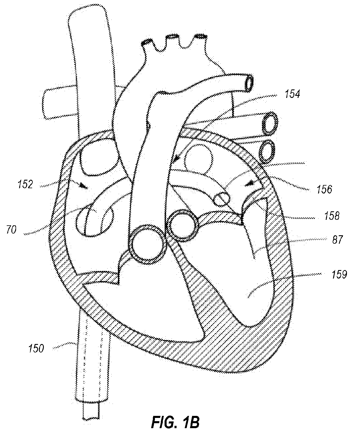
[0035]The present disclosure is directed to devices, systems, and methods for loading, delivering, positioning, and deploying a replacement heart valve device. Throughout this disclosure, many examples are described in the context of a replacement artificial mitral valve. One of skill in the art will understand, however, that the described components, features, and principles may also be utilized in other applications. For example, at least some of the embodiments described herein may be utilized for loading, delivering, positioning, and deploying an artificial valve for replacing a pulmonary, aortic, or tricuspid valve.

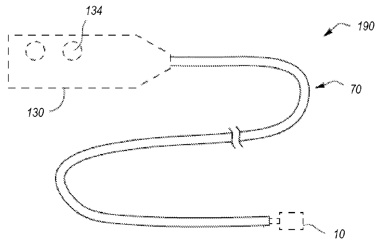
[0036]Moreover, it will be understood that at least some of the delivery system embodiments described herein may be utilized in conjunction with other interventional devices, including valve repair devices, annuloplasty devices, clip devices, and other interventional devices not necessarily configured as a replacement valve. Thus, although the following d...


PUM


Abstract

The present disclosure describes devices, systems, and methods for loading, delivering, positioning, and deploying an artificial heart valve device at the mitral annulus. A delivery system includes a delivery member coupled to a handle assembly and extending distally from the handle assembly. The valve device is attached at the distal end of the delivery member, and is constrained within a valve cover of an outer sheath. A delivery catheter is configured to advance the valve relative to the outer sheath, and a suture catheter includes sutures / tethers which maintain proximal tension on the valve prior to deployment.

Description

CROSS-REFERENCE TO RELATED APPLICATIONS[0001]This application claims the benefit of and priority to: U.S. Provisional Patent Application Ser. No. 62 / 404,511, filed Oct. 5, 2016 and titled “Systems and Methods for Loading and Deploying an Intravascular Device”; U.S. Provisional Patent Application Ser. No. 62 / 430,149, filed on Dec. 5, 2016 and titled “Systems and Methods for Loading and Deploying an Intravascular Device”; U.S. Provisional Patent Application Ser. No. 62 / 436,922, filed Dec. 20, 2016 and titled “Systems and Methods for Loading and Deploying an Intravascular Device”; and U.S. Provisional Patent Application Ser. No. 62 / 462,776, filed on Feb. 23, 2017 and titled “Systems and Methods for Loading and Deploying an Intravascular Device,” the disclosures of which are incorporated herein by references in their entireties.BACKGROUND[0002]1. Field of the Invention[0003]The present disclosure generally relates to devices, systems, and methods for loading a replacement heart valve in...

Claims


Application Information

Patent Timeline
Patent Type & Authority Applications(United States)
IPC IPC(8): A61F2/24
CPCA61F2/2436A61F2002/9517A61F2002/9522A61F2210/0014A61F2/2409A61F2/2439A61F2/9525A61F2/9517A61F2/9522
Inventor VON OEPEN, RANDOLFMCNIVEN, SEAN A.VALENCIA, FRANCISCO
Owner CEPHEA VALVE TECH
Why Eureka
Try Eureka