Battery disconnecting device

a battery disconnecting and battery technology, applied in secondary cell servicing/maintenance, cell components, pulse techniques, etc., can solve the problems of increasing losses, current flowing through two diodes, and relatively slow switching time in comparison to power semiconductors, so as to reduce power loss and fast switching times

Active Publication Date: 2018-04-05
VOLKSWAGEN AG
View PDF4 Cites 9 Cited by
  • Summary
  • Abstract
  • Description
  • Claims
  • Application Information

AI Technical Summary

Benefits of technology

[0007]The invention is based on the technical objective of creating a battery disconnecting

Problems solved by technology

A drawback of relays is their relatively slow switching time in comparison to power semiconductors.
A disadvantage of this circuit is that the current alw

Method used


Image

  • Battery disconnecting device
  • Battery disconnecting device
  • Battery disconnecting device

Examples


Embodiment Construction

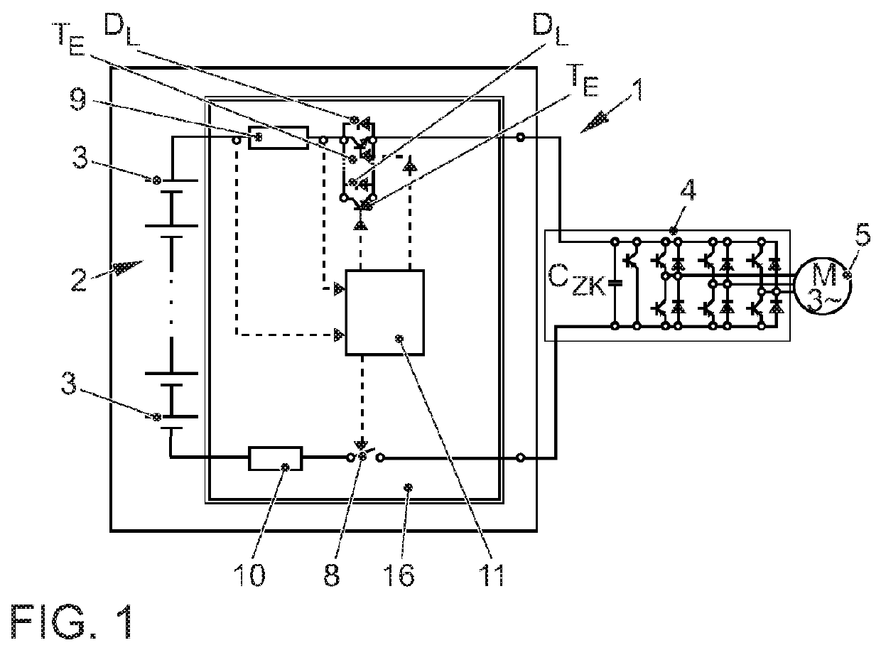
[0029]Before the invention is elaborated upon, the state of the art will first be explained making reference to FIGS. 4 and 5. The traction system 1 comprises a battery 2 having a plurality of series-connected battery cells 3, power electronics 4 with DC link capacitor CZK, an electric machine 5 as well as a battery disconnecting device 6. The battery disconnecting device 6 has a first relay 7 and a second relay 8 by means of which the plus line and the minus line can be switched on or off.

[0030]Moreover, the battery disconnecting device 6 has a current sensor 9, a fuse 10, a control unit 11, a precharging relay SVL and a precharging resistor RVL. The DC link capacitor CZK is charged with a moderate current via the precharging relay SVL and the precharging resistor RVL. For this purpose, first of all, the relay 7 is left open and the relay 8 as well as the precharging relay SVL are closed. Once the DC link capacitor CZK is charged, the relay 7 is closed and the precharging relay SVL...


PUM


Abstract

A battery disconnecting device has a first input and a second input to which a battery can be connected, whereby the disconnecting device also has a first output and a second output to which an electric component can be connected, whereby at least one first circuit breaker is arranged between the first input and the first output, and at least one second circuit breaker is arranged between the second input and the second output, whereby the first circuit breaker is at least a transistor and the second circuit breaker is a relay.

Description

BACKGROUND OF THE INVENTION[0001]The invention relates to a battery disconnecting device.[0002]Battery disconnecting devices are needed in order to systematically connect or disconnect a battery. In this context, the battery is, for instance, a high-voltage battery of a traction system in an electric or hybrid vehicle.[0003]Such a battery disconnecting device is disclosed, for example, in German patent application DE 10 2011 015 694 A1. Here, the battery disconnecting device has a first input as well as a second input to which that a battery can be connected, whereby the battery disconnecting device also has a first output and a second output to which an electric component can be connected. The electric component is, for instance, a power electronic system that serves to actuate an electric machine. A first circuit breaker in the form of a relay is arranged between the first input and the first output, while a second circuit breaker in the form of a relay is arranged between the sec...

Claims


Application Information

Patent Timeline
IPC IPC(8): H02J7/00H03K17/687H03K17/567H01M10/42H01M50/583
CPCH02J7/0068H03K17/687H03K17/567H01M10/42B60L58/18B60L58/21B60L3/0046H02J7/0024H01M50/583H03K17/122H03K17/127H02J7/0031Y02T10/70Y02E60/10
Inventor KUBE, ROLAND
Owner VOLKSWAGEN AG
Why Eureka
Try Eureka