On-board network system

a network system and network technology, applied in the field of on-board network systems, can solve the problems of not meeting the requirements, affecting the service life of the communication node,

Active Publication Date: 2018-04-05
TOYOTA JIDOSHA KK
View PDF5 Cites 27 Cited by
  • Summary
  • Abstract
  • Description
  • Claims
  • Application Information

AI Technical Summary

Benefits of technology

[0025]With the above configuration, when there are two or more physical communication routes between two gateway devices among the plurality of gateway devices, the priority is specified in advance for each of the communication routes. Therefore, when disruption of communications is detected, the communication route that does not include the communication line that causes disruption of communications is selected in order of priority, so that the second logical network can be easily reconstructed.

Problems solved by technology

However, if the ARP is used in the local network, it takes time to send and receive the ARP request and the ARP reply, and the network load may become considerably high, since each communication node transmits the ARP request by broadcasting.
Therefore, it may take a relatively long time for each communication node to grasp the reconstructed network.
Thus, the requirement may not be satisfied, according to the method using ARP or RIP.

Method used


Image

  • On-board network system
  • On-board network system
  • On-board network system

Examples


first embodiment

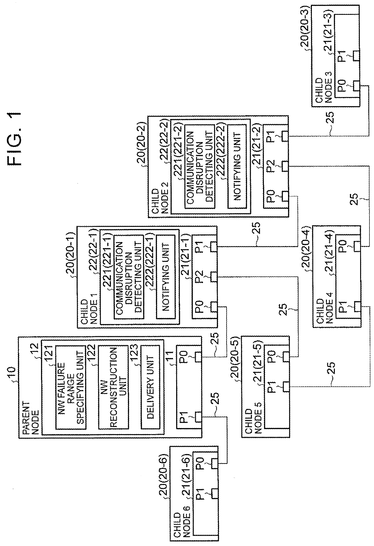
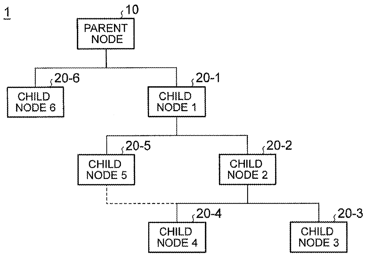
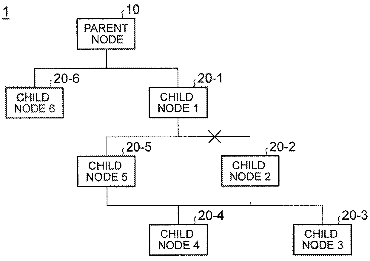
[0048]An on-board network system 1 according to the first embodiment includes a parent node 10, and a plurality of child nodes 20 physically connected by communication lines 25 in a hierarchical fashion, using the parent node 10 as a source node, as a plurality of nodes of which each pair of nodes are physically connected by a single communication line, such that they can communicate with each other, as will be described later. In the on-board network system 1, the parent node 10 and the plurality of child nodes 20 constitute a logical tree-type network having the parent node 10 as a source node, and mutual communications are conducted based on information (such as a MAC address table or a routing table, which will be described later) concerning the configuration of the network.

[0049]Referring initially to FIG. 1, FIG. 2A, and FIG. 2B, the configuration of the on-board network system 1 according to this embodiment will be described.

[0050]FIG. 1 is a block diagram schematically showi...

second embodiment

[0138]Next, a second embodiment will be described.

[0139]An on-board network system 2 according to this embodiment includes a plurality of gateway devices 30, as a plurality of nodes that are physically connected such that each pair of the nodes are connected by a single communication line, and these nodes can communicate with each other, as will be described later. The gateway devices 30 belong to a plurality of local networks LN1-LN3, respectively, and are operable to relay communications among the local networks LN1 to LN3. In the on-board network system 2, a logical network is constructed by use of only one communication route determined from two or more communication routes between two gateway devices 30 among the plurality of gateway devices 30, and communications between the gateway devices 30 are conducted based on information concerning the configuration of the network.

[0140]Referring initially to FIG. 11, the configuration of the on-board network system 2 according to this ...


PUM


Abstract

An on-board network system includes: communication lines; a plurality of nodes, each of the nodes being directly and physically connected to at least one of the other nodes by the communication lines, the nodes including loop nodes physically connected to a loop by the communication lines, the nodes constituting a first logical network in which the nodes are connected with each other via one route through the communication lines; a communication disruption detecting unit configured to detect disruption of communications via the communication lines; a network reconstruction unit configured to reconstruct a second logical network when the disruption of communications is detected by the communication disruption detecting unit, the second logical network not including a communication line that causes the disruption; and a delivery unit configured to deliver the information of the second logical network to the nodes.

Description

INCORPORATION BY REFERENCE[0001]The disclosures of Japanese Patent Application Nos. 2016-196614 and 2016-239701 filed Oct. 4, 2016 and Dec. 9, 2016, respectively, including the specifications, drawings and abstracts are incorporated herein by reference in their entireties.BACKGROUND1. Technical Field[0002]The disclosure relates to an on-board network system.2. Description of Related Art[0003]A plurality of nodes on a network based on the Ethernet (registered trademark) communication protocol can obtain MAC addresses from each other, based on an IP address of other node, by use of Address Resolution Protocol (ARP) (for example, see. Japanese Patent Application Publication No. 2006-333260 (JP 2006-333260 A)). More specifically, if one node sends an APR request onto the network by broadcasting, and another node corresponding to a target IP address in the ARP request receives the ARP request, the other node sends an ARP reply including its own MAC address to the one node by unicasting. ...

Claims


Application Information

Patent Timeline
Patent Type & Authority Applications(United States)
IPC IPC(8): H04L12/703H04L12/707H04L45/28H04L45/24
CPCH04L45/28H04L45/22H04L61/103H04L67/12H04L45/48
Inventor MATSUI, TAKESHIFURUKAWA, HISASHI
Owner TOYOTA JIDOSHA KK
Why Eureka
Try Eureka