Rotary type magnetic coupling device

Active Publication Date: 2018-04-12
TDK CORPARATION
View PDF4 Cites 10 Cited by
  • Summary
  • Abstract
  • Description
  • Claims
  • Application Information

AI Technical Summary

Benefits of technology

[0015]The present invention has been made in view of the above problems, and an object thereof is to provide a rotary type magne

Problems solved by technology

However, energizing is performed by sliding the contact part in the above contact type, so that the contact part is abraded, which may result in failing to perform power transmission.
At this time, magnetic flux caused by power transmission may affect the signal transmission.
However, in a case where the technologies disclosed in JP 2011-003947A and JP 2013-169122A are each applied to a rotator, when the power transmitting side or power receiving side is rotated to change the angle between them, the axis of the coil that transmits a signal and the axis of the coil that re

Method used


Image

  • Rotary type magnetic coupling device
  • Rotary type magnetic coupling device
  • Rotary type magnetic coupling device

Examples


Embodiment Construction

[0034]Preferred embodiments of the present invention will now be explained in detail with reference to the drawings.

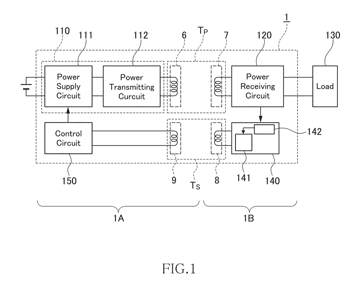
[0035]FIG. 1 is a block diagram schematically illustrating the entire configuration of a rotary type magnetic coupling device according to an embodiment of the present invention.

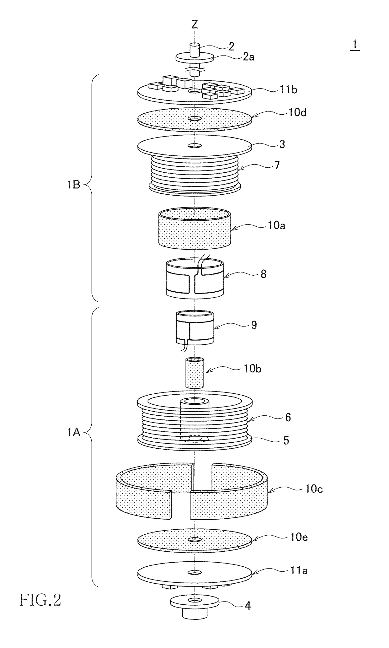
[0036]As illustrated in FIG. 1, a rotary type magnetic coupling device 1 is constituted of a combination of a power transmitting unit 1A and a power receiving unit 1B. The rotary type magnetic coupling device 1 is configured to transmit electric power from the power transmitting unit 1A to the power receiving unit 1B by wireless.

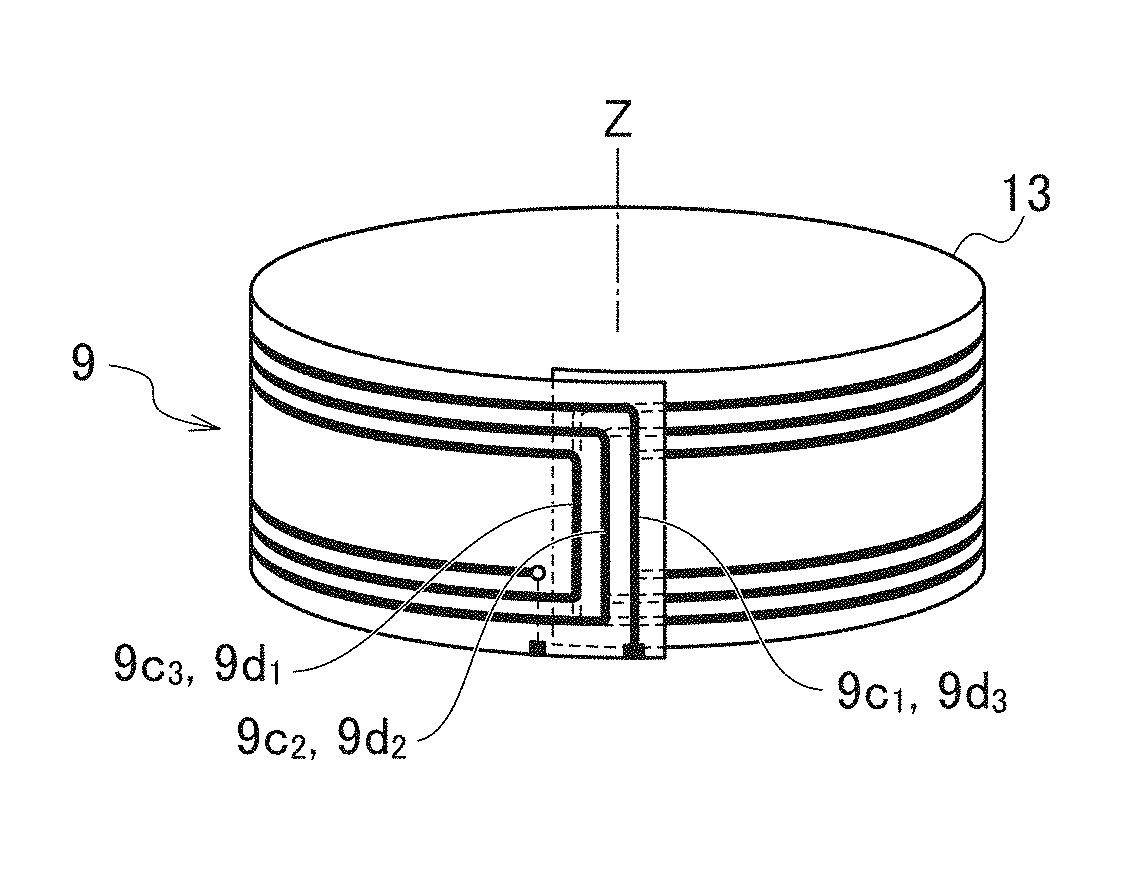
[0037]The power transmitting unit 1A includes a power transmitting circuit 110, a power transmitting coil 6, a signal receiving coil 9, and a control circuit 150. The power transmitting circuit 110 converts an input DC voltage into an AC voltage of, e.g., 100 kHz and outputs it. The power transmitting coil 6 generates an AC magnetic flux using the AC voltage. The signal...


PUM


Abstract

Disclosed herein is a rotary type magnetic coupling device used for a rotator. The rotary type magnetic coupling device includes first and second coils magnetically coupled to each other, and third and fourth coils magnetically coupled to each other. The coil axes of the first and second coils extend in a rotary axis direction of the rotator, and the coil axes of the third and fourth coils radially extend in a radial direction substantially orthogonal to the rotary axis of the rotator.

Description

BACKGROUND OF THE INVENTIONField of the Invention[0001]The present invention relates to a rotary type magnetic coupling device and, more particularly, to a device that transmits electric power or a signal to a rotator by wireless.Description of Related Art[0002]Rotary type power transmission devices used for electric power transmission to a rotator are suitably used for power supply to, e.g., a multi-axis industrial robot arm, a monitoring camera, a device on a rotary stage, and the like. Conventionally, a contact-type slip ring is used in the rotary type power transmission devices. The slip ring is a mechanism that transmits electric power to a rotary side by bringing a brush provided in a fixed side into contact with a sliding surface of a metal ring installed in the rotary side.[0003]However, energizing is performed by sliding the contact part in the above contact type, so that the contact part is abraded, which may result in failing to perform power transmission. Therefore, a no...

Claims


Application Information

Patent Timeline
IPC IPC(8): H01F27/34H02J50/10H01F27/28H01F27/24H01F27/32H01F38/14
CPCH01F27/34H02J50/10H01F27/2804H01F27/24H01F27/325H01F38/14H02J50/40H01F27/2823H01F27/366H01F38/18H01F2038/143H02J50/005H02J50/70H01F27/36
Inventor HANABUSA, KAZUYOSHIURANO, TAKASHI
Owner TDK CORPARATION
Why Eureka
Try Eureka