Rotary type magnetic coupling device

a coupling device and magnetic coupling technology, applied in the direction of coils, transformers/inductance details, inductances, etc., can solve the problems of power transmission failure and failure to obtain stable output characteristics

Active Publication Date: 2018-04-12
TDK CORPARATION
View PDF0 Cites 14 Cited by
  • Summary
  • Abstract
  • Description
  • Claims
  • Application Information

AI Technical Summary

Benefits of technology

[0006]The present invention has been made in view of the above problems, and an object thereof is to provide a rotary type magnetic coupling device used for a rotator capable of obtaining stable output characteristics even when the positional relationship between coils is changed in accordance with the rotation amount of the rotator.

Problems solved by technology

However, energizing is performed by sliding the contact part in the above contact type, so that the contact part is abraded, which may result in failing to perform power transmission.
In the technology disclosed in JP 2007-208201A, however, there exists a gap between conducting wires each connecting the upper-side conducting wire and lower-side conducting wire in each of power feeding and power receiving coils, so that the amount of magnetic flux that intersects the power receiving coil is changed with a change in the rotational direction position of the power feeding coil relative to the power receiving coil, resulting in failing to obtain stable output characteristics.

Method used


Image

  • Rotary type magnetic coupling device
  • Rotary type magnetic coupling device
  • Rotary type magnetic coupling device

Examples


Embodiment Construction

[0024]Preferred embodiments of the present invention will now be explained in detail with reference to the drawings.

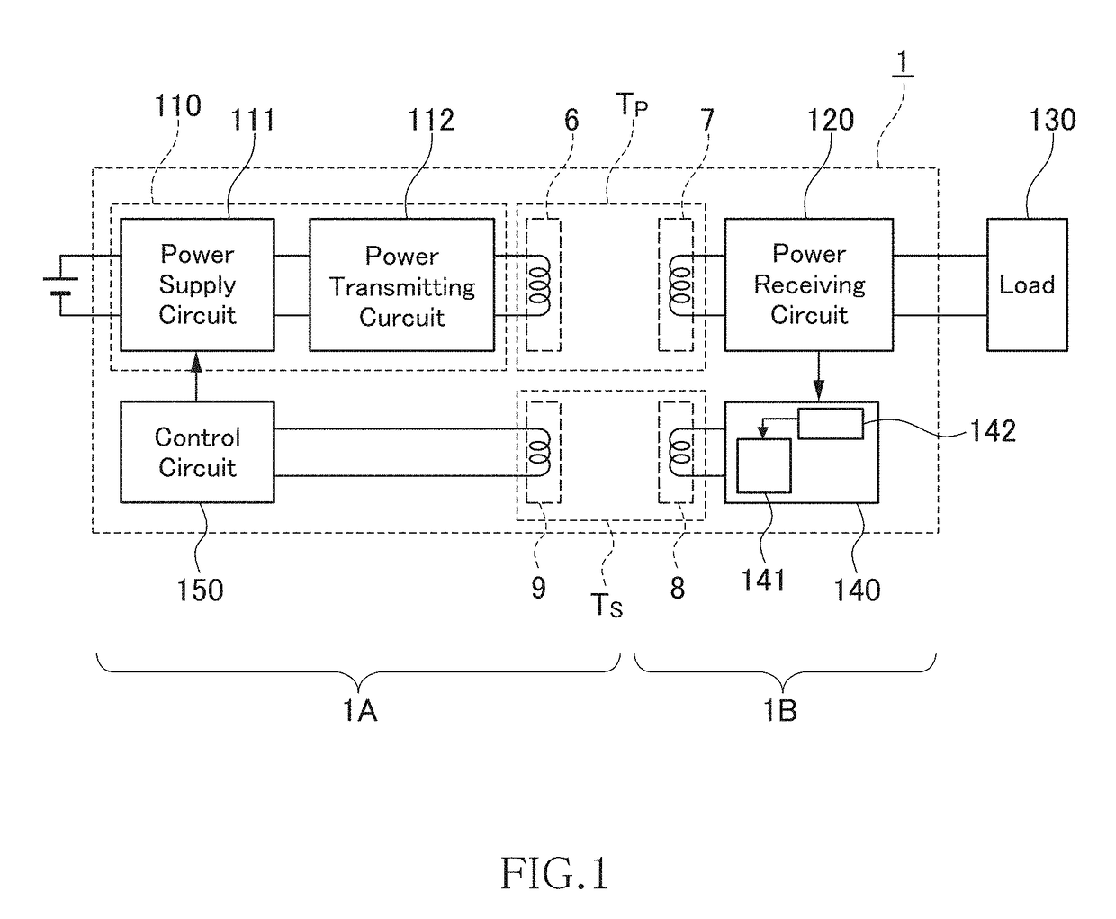
[0025]FIG. 1 is a block diagram schematically illustrating the entire configuration of a rotary type magnetic coupling device according to an embodiment of the present invention.

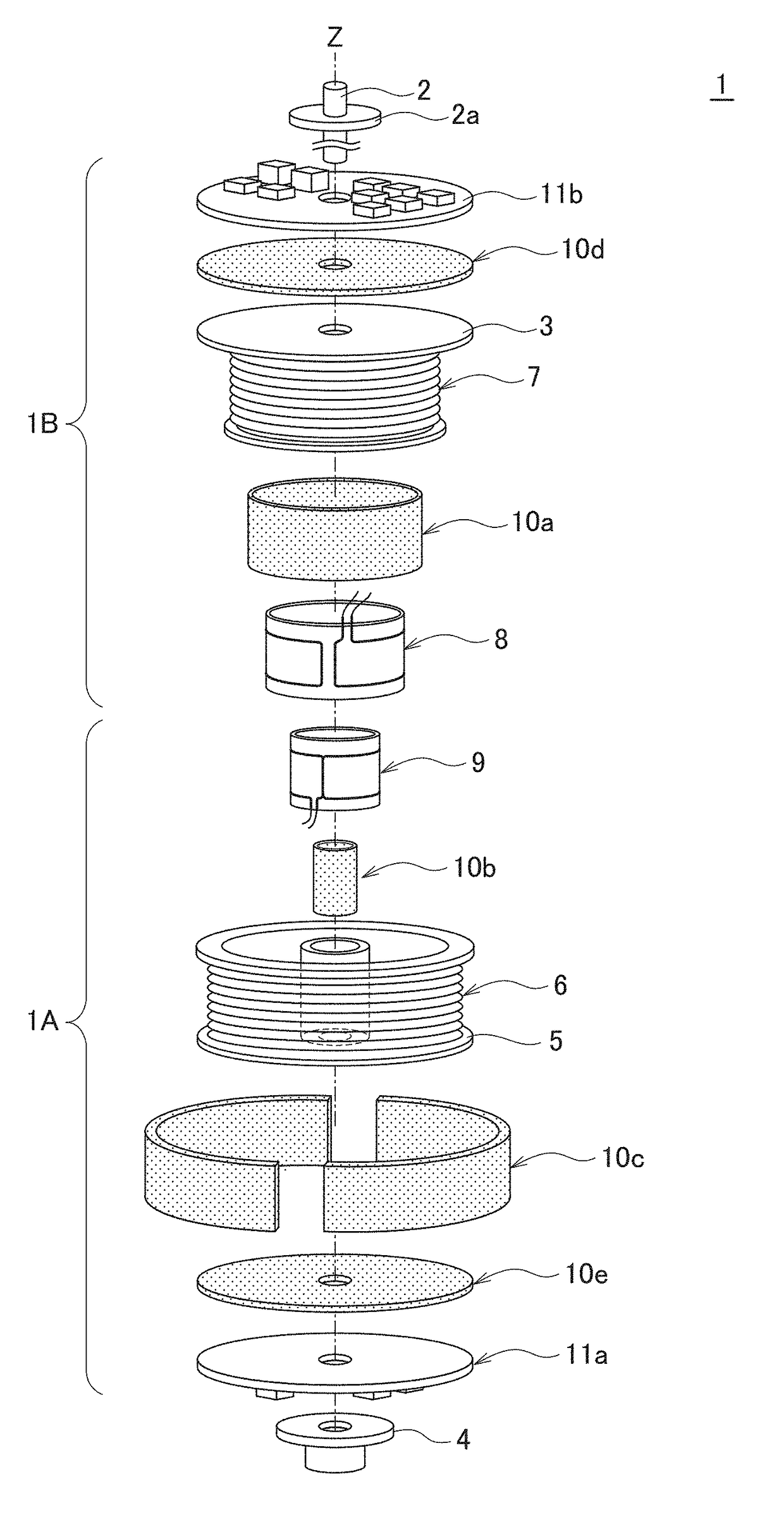
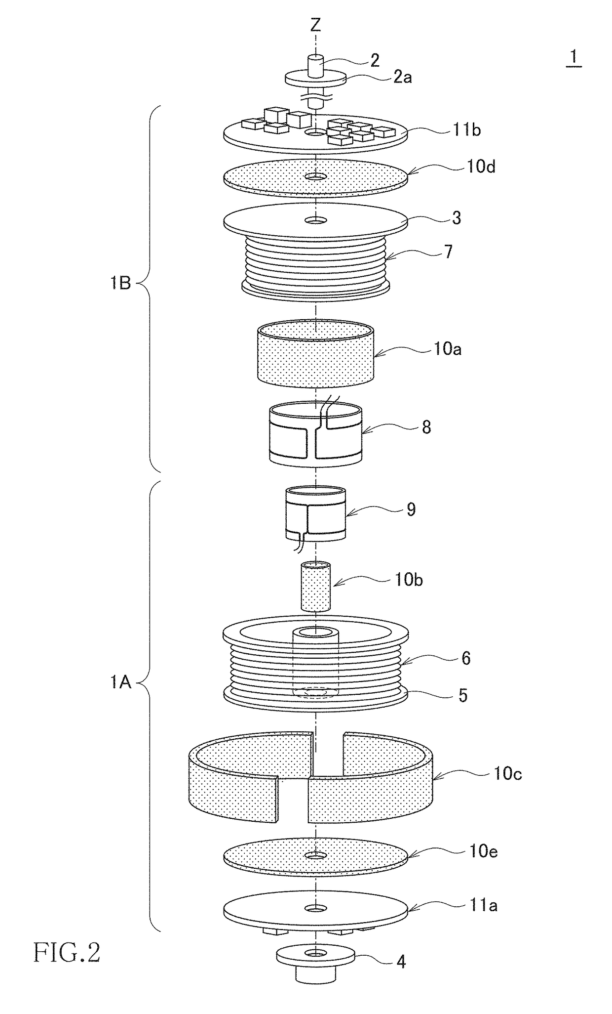
[0026]As illustrated in FIG. 1, a rotary type magnetic coupling device 1 is constituted of a combination of a power transmitting unit 1A and a power receiving unit 1B. The rotary type magnetic coupling device 1 is configured to transmit electric power from the power transmitting unit 1A to the power receiving unit 1B by wireless.

[0027]The power transmitting unit 1A includes a power transmitting circuit 110, a power transmitting coil 6, a signal receiving coil 9, and a control circuit 150. The power transmitting circuit 110 converts an input DC voltage into an AC voltage of, e.g., 100 kHz and outputs it. The power transmitting coil 6 generates an AC magnetic flux using the AC voltage. The signal...


PUM

PropertyMeasurementUnit
DC voltageaaaaaaaaaa
frequencyaaaaaaaaaa
frequencyaaaaaaaaaa

Abstract

Disclosed herein is a rotary type magnetic coupling device including first and second coils magnetically coupled to each other used for a rotator. Each of the first and second coils is a loop-shaped having an opening surrounding a rotary axis of the rotator. Each of the first and second coils includes first and second wiring parts extending in a peripheral direction of the rotator, a third wiring part bent in the rotary axis direction from one end of the first and second wiring parts, and a fourth wiring part bent in the rotary axis direction from other end of the first and second wiring parts. At least one of the first and second coils is configured such that the third and fourth wiring parts match or overlap each other when viewed in a radial direction substantially orthogonal to the rotary axis.

Description

BACKGROUND OF THE INVENTIONField of the Invention[0001]The present invention relates to a rotary type magnetic coupling device and, more particularly, to a device that transmits electric power or a signal to a rotator by wireless.Description of Related Art[0002]Rotary type power transmission devices used for electric power transmission to a rotator are suitably used for power supply to, e.g., a multi-axis industrial robot arm, a monitoring camera, a device on a rotary stage, and the like. Conventionally, a contact-type slip ring is used in the rotary type power transmission devices. The slip ring is a mechanism that transmits electric power to a rotary side by bringing a brush provided in a fixed side into contact with a sliding surface of a metal ring installed in the rotary side.[0003]However, energizing is performed by sliding the contact part in the above contact type, so that the contact part is abraded, which may result in failing to perform power transmission. Therefore, a no...

Claims


Application Information

Patent Timeline
Patent Type & Authority Applications(United States)
IPC IPC(8): H01F38/18H01F38/14H01F27/32H01F5/00
CPCH01F38/18H01F38/14H01F27/325H01F5/003H01F2038/143
Inventor HANABUSA, KAZUYOSHIURANO, TAKASHI
Owner TDK CORPARATION
Why Eureka
Try Eureka