Brake hydraulic pressure control device and Anti-lock brake system

Active Publication Date: 2018-04-19
ROBERT BOSCH GMBH
View PDF10 Cites 2 Cited by
  • Summary
  • Abstract
  • Description
  • Claims
  • Application Information

AI Technical Summary

Benefits of technology

[0007]In the brake hydraulic pressure control device according to the present invention, the base body is fixed to the connecting portion which connects the trunk portion and the wheel of the motorcycle. That is, the base body is not mounted on the trunk portion. Accordingly, for example, necessity of changing a layout of respective parts of the trunk portion depending on whether or not the brake hydraulic pressure control device is incorporated into the brake system is reduced, and necessity of arranging a pipe of the anti-lock brake

Problems solved by technology

That is, the above-mentioned brake hydraulic pressure control device has drawbacks th

Method used


Image

  • Brake hydraulic pressure control device and Anti-lock brake system
  • Brake hydraulic pressure control device and Anti-lock brake system
  • Brake hydraulic pressure control device and Anti-lock brake system

Examples


first embodiment

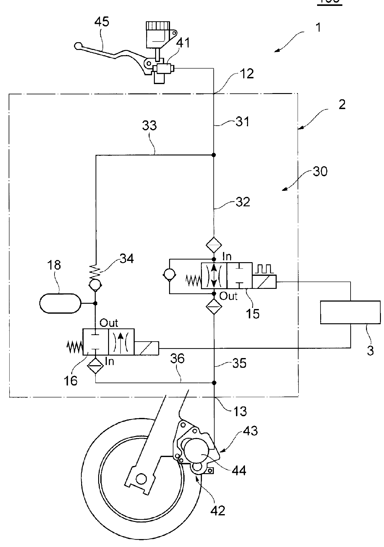
[0023]Hereinafter, an anti-lock brake system is described.

[0024]The configuration of the anti-lock brake system according to the first embodiment is described.

[0025]FIG. 1 is a system block diagram showing the configuration of the anti-lock brake system according to the first embodiment of the present invention.

[0026]As shown in FIG. 1, an anti-lock brake system 1 is mounted on a motorcycle 100 (two-wheeled vehicle or three-wheeled vehicle), and includes a brake hydraulic pressure control device 2, and a controller 3 (ECU) which electrically controls the brake hydraulic pressure control device 2. By controlling the brake hydraulic pressure control device 2 by the controller 3, an anti-lock brake control of the motorcycle 100 is performed. The anti-lock brake system 1 includes at least one brake hydraulic pressure control device 2. The anti-lock brake system 1 may particularly preferably be a pumpless anti-lock brake system.

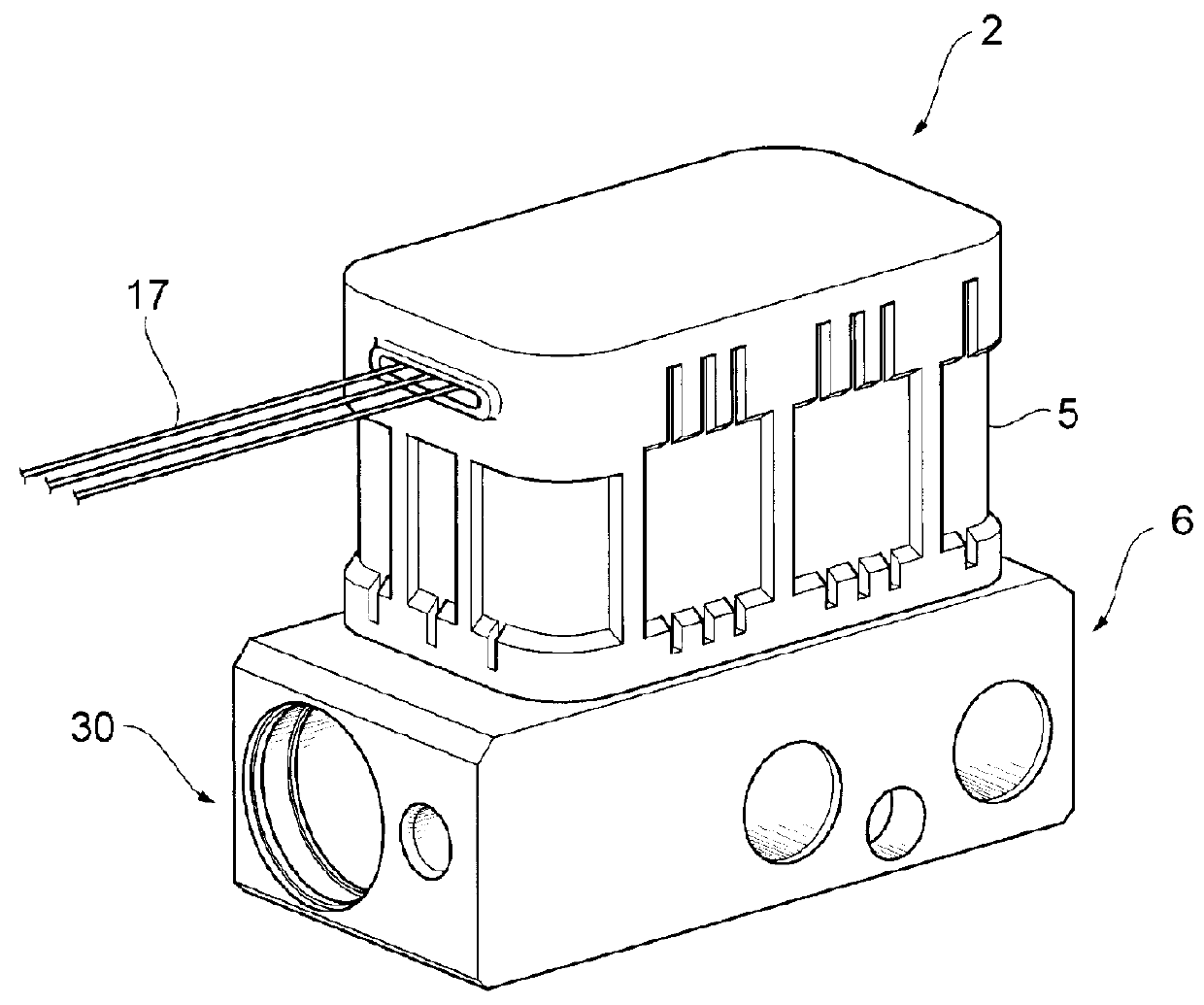
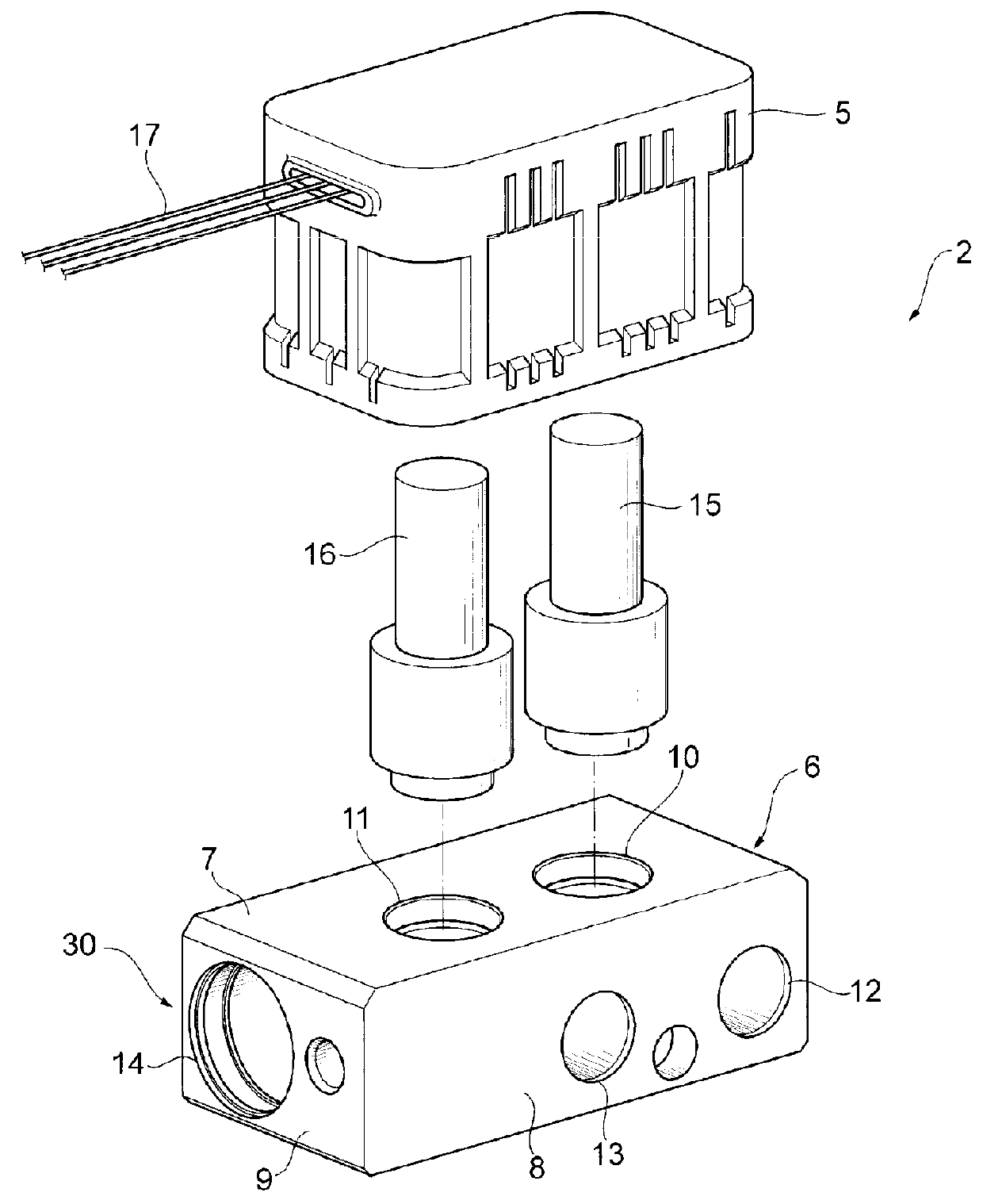
[0027]The brake hydraulic pressure control device 2 include...

second embodiment

[0077]An anti-lock brake system is described hereinafter.

[0078]The description which overlaps with the description of the anti-lock brake system according to the first embodiment is omitted when appropriate.

[0079]The detail of mounting of the brake hydraulic pressure control device of the anti-lock brake system according to the second embodiment is described.

[0080]FIG. 13 is a side view of an essential part for explaining one example of a state where the brake hydraulic pressure control device of the anti-lock brake system according to the second embodiment of the present invention is mounted on a motorcycle.

[0081]As shown in FIG. 13, the brake hydraulic pressure control device 2 includes a protective cover 122 which covers the base body 6 and the valve case 5. The protective cover 122 may cover whole brake hydraulic pressure control device 2 or only a part of the brake hydraulic pressure control device 2. For example, the protective cover 122 may preferably cover at least a lower ...


PUM


Abstract

A brake hydraulic pressure control device (2) controls a fluid pressure of a brake fluid supplied to wheel cylinders mounted on brake calipers (107, 114) of a motorcycle (100). The brake hydraulic pressure control device (2) includes: a base body in which flow passages are formed; and valves which open or close the flow passages. The base body is fixed below a spring in connecting portions (130A, 130B) which connect a trunk portion (101) of the motorcycle (100) and a wheels (front wheel (106), rear wheel (113)) to each other.

Description

BACKGROUND OF THE INVENTION[0001]The present invention relates to a brake hydraulic pressure control device for controlling a hydraulic pressure of a brake fluid supplied to a wheel cylinder mounted on a brake caliper of a motorcycle, and an anti-lock brake system in which the brake hydraulic pressure control device is incorporated.[0002]As a conventional anti-lock brake system, for example, there has been known an anti-lock brake system in which a brake hydraulic pressure control device having a base body in which a flow passage communicating with a wheel cylinder is formed and a valve which opens or closes the flow passage is incorporated. In such a brake hydraulic pressure control device, the base body is mounted on a trunk portion of a motorcycle (two-wheeled vehicle or three-wheeled vehicle) (see JP-A-2007-216814, for example).SUMMARY OF THE INVENTION[0003]In the above-mentioned brake hydraulic pressure control device, it is necessary to ensure a space for mounting the brake hy...

Claims


Application Information

Patent Timeline
IPC IPC(8): B60T8/36B60T8/32
CPCB60T8/3685B60T8/3225B60T8/42
Inventor ADACHI, EIJIATSUSHI, HIROAKIIKEDA, SHIGEKI
Owner ROBERT BOSCH GMBH
Why Eureka
Try Eureka