
Multi-frequency power amplifying device

A power amplification and multi-band technology, which is applied to components of amplification devices, high-frequency amplifiers, radio frequency amplifiers, etc., can solve the difficulty of meeting the requirements of efficiency and linearity, the difficulty of both efficiency and linearity in power amplifier architecture, and the difficulty of system design and other issues to achieve the effect of improving design performance, increasing efficiency and reducing costs

Active Publication Date: 2014-06-25
HUAWEI TECH CO LTD
View PDF0 Cites 13 Cited by
  • Summary
  • Abstract
  • Description
  • Claims
  • Application Information

AI Technical Summary

Problems solved by technology

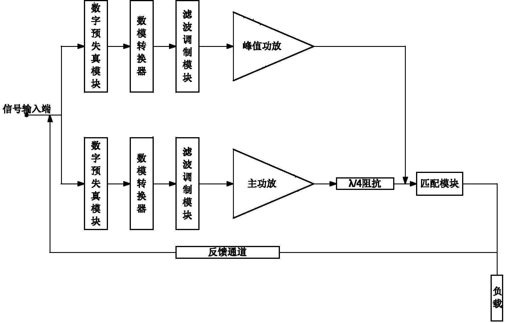
[0004] With the development of communication technology, technologies such as multi-band and ultra-wideband have put forward higher requirements for power amplifiers, resulting in additional figure 1 The amplifier architecture of the example has great difficulty in balancing efficiency and linearity
For example, attach figure 1 The example power amplifier architecture may be able to meet the efficiency and linearity requirements of signal A with frequency band f, but it is difficult to meet the efficiency and linearity requirements of signal B with frequency band f', and vice versa; A and signal B requirements, the efficiency will be very low, which brings great difficulties to the system design

Method used


Image

  • Multi-frequency power amplifying device
  • Multi-frequency power amplifying device
  • Multi-frequency power amplifying device

Examples


Embodiment Construction

[0049] The following will clearly and completely describe the technical solutions in the embodiments of the present invention with reference to the accompanying drawings in the embodiments of the present invention. Obviously, the described embodiments are only some, not all, embodiments of the present invention. All other embodiments obtained by those skilled in the art based on the embodiments of the present invention belong to the protection scope of the present invention.

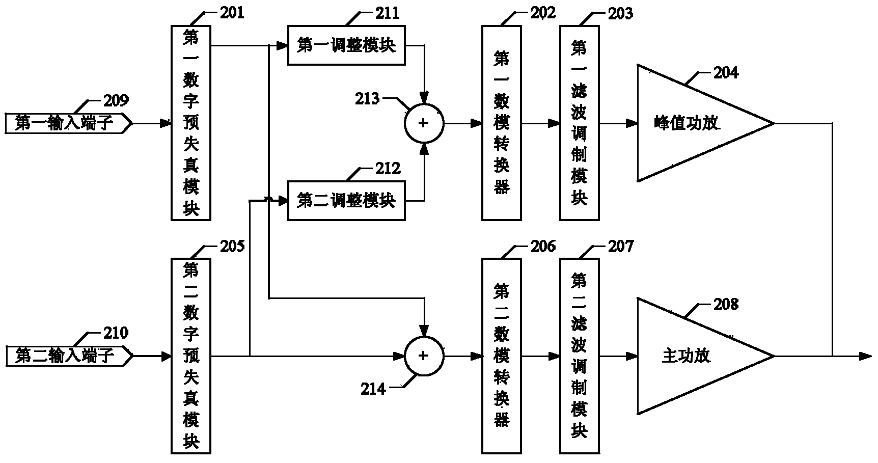
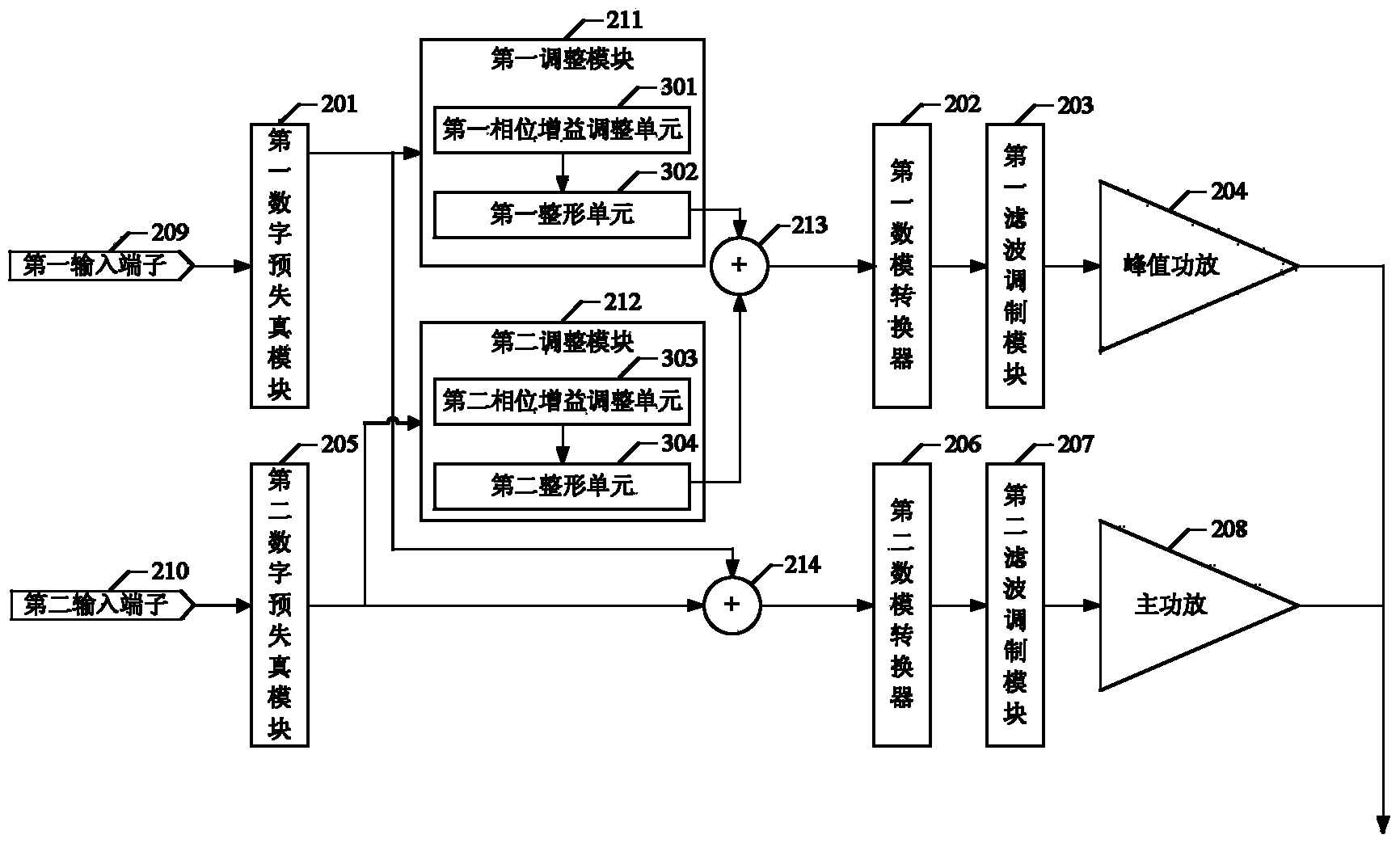
[0050] Please refer to the attached figure 2 , is a schematic structural diagram of a multi-band power amplification device provided by an embodiment of the present invention. attached figure 2 The exemplary multi-band power amplification device mainly includes a first digital pre-distortion module 201, a first digital-to-analog converter 202, a first filter modulation module 203, a peak power amplifier 204 connected to the first filter modulation module 203, a second digital pre-distortion module 20...


PUM


Abstract

The invention provides a multi-frequency power amplifying device which satisfies the requirements of improving efficiency and linearization. The multi-frequency power amplifying device comprises a first input terminal, a second input terminal, a first adjusting module, a second adjusting module, a first summator and a second summator, wherein the first input terminal receives the signal of frequency f1 and then outputs to a first digital predistortion module, the second input terminal receives the signal of frequency f2 and then outputs to a second digital predistortion module, the first adjusting module adjusts a first signal and outputs the first signal to the first summator, the second adjusting module adjusts a third signal and outputs the third signal to the first summator, the first summator combines the signal adjusted by the second adjusting module and the signal output by the first adjusting module and outputs the combined signals to a first digital-analog converter, and the second summator combines the second signal and the fourth signal and outputs the combined signal to the second digital-analog converter. The multi-frequency power amplifying device improves the design performance of frequency-span amplification, reduces amplification type and reduces cost.

Description

technical field [0001] The invention relates to the field of mobile communication, in particular to a multi-band power amplification device. Background technique [0002] In a wireless communication system, the power amplifier is located at the front end of the transmitter, and its main function is to amplify the signal and meet the system's requirements for the power of the transmitted signal. In order to ensure a certain modulation accuracy and not interfere with other systems, higher requirements are put forward for the linearization technology of the power amplifier. Although related technologies such as power amplifiers have always been research hotspots in the field of communication, the requirements for power amplifiers still revolve around efficiency and linearity, mainly involving various architectures and technologies of the power amplifier itself, as well as algorithms for corresponding linearization techniques, such as , Doherty technology has achieved great suc...

Claims


Application Information

Patent Timeline
Patent Type & Authority Applications(China)
IPC IPC(8): H03F1/07
CPCH03F1/0288H03F1/3247H03F1/3252H03F3/189H03F3/19H03F3/245H03F2200/111H03F2200/165H03F2200/451
Inventor 王昆吴迪朱尔霓
Owner HUAWEI TECH CO LTD
Learn More