Quantum dot luminophore

Active Publication Date: 2018-04-26
TSING YAN TECH CO LTD
View PDF2 Cites 6 Cited by
  • Summary
  • Abstract
  • Description
  • Claims
  • Application Information

AI Technical Summary

Benefits of technology

[0008]In view of the fact that commercial phosphors applied in LED component always show the most important drawback of light re-absorption, primary objective of the present invention is to provide a quantum dot luminophore capable of being implemented in the LED component for replacing the commercial phosphors. The quantum dot luminophore comprises at least one luminescent core, a spacer layer, an encapsulation layer, and a plurality of quantum dots. Particularly, the luminescent core is designed to emit a red light after being excited by an incident blue light, and the quantum dots are

Problems solved by technology

However, the most important drawback of white LED component of this type is the expensive manufacture cost.
From Table (1), it is understood that most of the red and blue phosphors have the important drawback of being difficult to be synthesized.
Moreover, the red and b

Method used


Image

  • Quantum dot luminophore
  • Quantum dot luminophore
  • Quantum dot luminophore

Examples


first embodiment

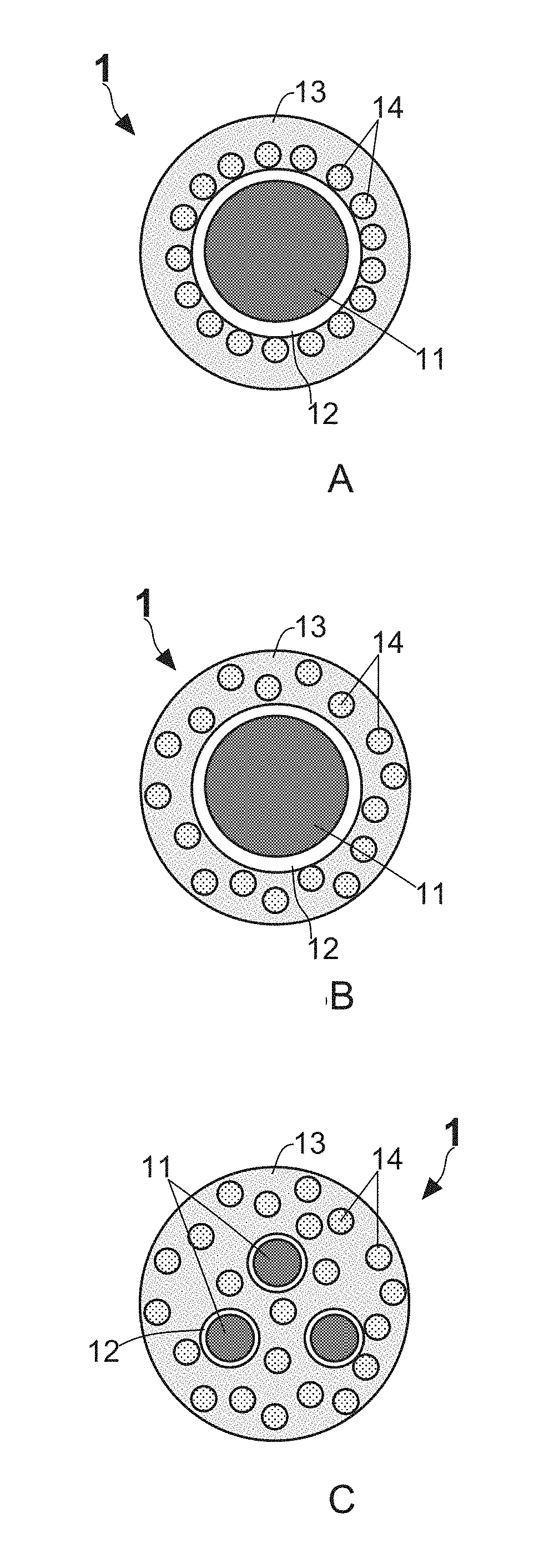
[0028]Please refer to FIG. 3A, FIG. 3B, and FIG. 3C, which illustrate cross-sectional side diagrams for depicting a first embodiment of a quantum dot luminophore according to the present invention. Moreover, corresponding HRTEM images of the three quantum dot luminophores in FIG. 3A, FIG. 3B, and FIG. 3C are provided in FIG. 4A, FIG. 4B, and FIG. 4C. In the first embodiment, the quantum dot luminophore 1 comprises at least one luminescent core 11, a spacer layer 12, an encapsulation layer 13, and a plurality of quantum dots 14. According to the particular design of the present invention, the luminescent core 11 is able to emit a first color light after being excited by a short-wavelength light such as blue light, and the quantum dots 14 are configured to irradiate a second color light by the illumination of the short-wavelength light and / or the first color light.

[0029]Based on the basic design of the first embodiment, the luminescent core 11 is covered and enclosed by the spacer lay...

second embodiment

[0041]Please refer to FIG. 9A, FIG. 9B, and FIG. 9C, which illustrate cross-sectional side diagrams for depicting a second embodiment of the quantum dot luminophore of the present invention. In the second embodiment, the quantum dot luminophore 1 comprises at least one luminescent core 11a, a spacer layer 12a, an encapsulation layer 13a, and a plurality of quantum dots 14a, wherein the luminescent core 11a is covered and enclosed by the spacer layer 12a, and the encapsulation layer 13a further covers and encloses the spacer layer 12a. Moreover, the quantum dots 14a are spread in the encapsulation layer 13 and locate between the encapsulation layer 13 and the spacer layer 12. For instance, FIG. 9A indicates that the quantum dots 14a are regularly provided on the outer surface of the spacer layer 12a and enclosed by the encapsulation layer 13a. Moreover, from FIG. 9B, it is understood that the quantum dots 14a are also be irregularly doped in the encapsulation layer 13. On the other h...


PUM


Abstract

A quantum dot luminophore comprising at least one luminescent core, a spacer layer, an encapsulation layer, and a plurality of quantum dots is disclosed. The luminescent core is designed to emit a red light after being excited by an incident blue light, and the quantum dots are configured to irradiate a green light by the illumination of the blue light and/or the red light. In the present invention, the quantum dots are particularly used to cover or surround the luminescent core for solving the light re-absorption. By such arrangement, even though part of incident blue light (about 10-30%) may be reflected by the luminescent core made of phosphor materials, the reflected blue light still can also be recycled by the quantum dots surrounding the luminescent core, such that the light conversion efficiency and emission intensity of the luminescent core are hence increased because the loss of blue light is decreased.

Description

BACKGROUND OF THE INVENTION1. Field of the Invention[0001]The present invention relates to the technology field of nano-crystalline materials, and more particularly to a quantum dot luminophore.2. Description of the Prior Art[0002]Light-emitting diode (LED), one kind of lighting element, is widely implemented in various illumination devices used in human life because of its advantages such as small size and long service life.[0003]There are two major types of white LED components. One is mainly constituted by a red LED die, a green LED die and a blue LED die and capable of emitting a white light with high color rendering index (CRI). However, the most important drawback of white LED component of this type is the expensive manufacture cost. White LED component of another one type is called phosphor-converted LED (PC-LED), which commonly comprises a short-wavelength LED die, red phosphor powders and green phosphor powders. It is worth explaining that the short-wavelength LED die can b...

Claims


Application Information

Patent Timeline
IPC IPC(8): C09K11/70H01L33/06H01L33/08H01L33/56
CPCC09K11/70H01L33/06H01L33/08H01L33/56H01L33/502
Inventor CHEN, YING-FANGCHEN, HSUEH-SHIH
Owner TSING YAN TECH CO LTD
Why Eureka
Try Eureka