
Wavelength conversion components and laser light sources

A technology of wavelength conversion and components, which is applied in optics, instruments, projection devices, etc., can solve the problems of high-power laser use conditions, low thermal conductivity of silica gel, low temperature, etc., to ensure thermal stability and light conversion efficiency, Guaranteed heat exchange efficiency and high heat resistance

Active Publication Date: 2022-03-15
QINGDAO HISENSE LASER DISPLAY CO LTD
View PDF5 Cites 0 Cited by
  • Summary
  • Abstract
  • Description
  • Claims
  • Application Information

AI Technical Summary

Problems solved by technology

[0004] (1) Use silica gel as a carrier to fix the phosphor on the substrate; mix the phosphor with silica gel, and then stick it on the substrate; due to the low thermal conductivity of silica gel and the low maximum temperature of silica gel, it cannot meet the requirements The use conditions of high-power lasers; in addition, due to the low thermal conductivity of silica gel, when the high-energy laser beam is irradiated on the phosphor, the temperature diffuses slowly, resulting in a higher temperature of the phosphor, thereby reducing the conversion efficiency of light
[0005] (2) Use glass or ceramics as a carrier to fix the phosphor powder on the substrate; mix the glass or ceramics with the phosphor powder, heat-melt and sinter and solidify to form a phosphor layer, and then fix the fixed phosphor layer on the substrate with silica gel; but The optical efficiency of the phosphor layer is low. In addition, due to the low thermal conductivity of silica gel, when the high-energy laser beam is irradiated on the phosphor, the temperature diffuses slowly, causing the temperature of the phosphor to be higher, thereby reducing the light intensity. Conversion efficiency

Method used


Image

  • Wavelength conversion components and laser light sources
  • Wavelength conversion components and laser light sources
  • Wavelength conversion components and laser light sources

Examples


Embodiment 1

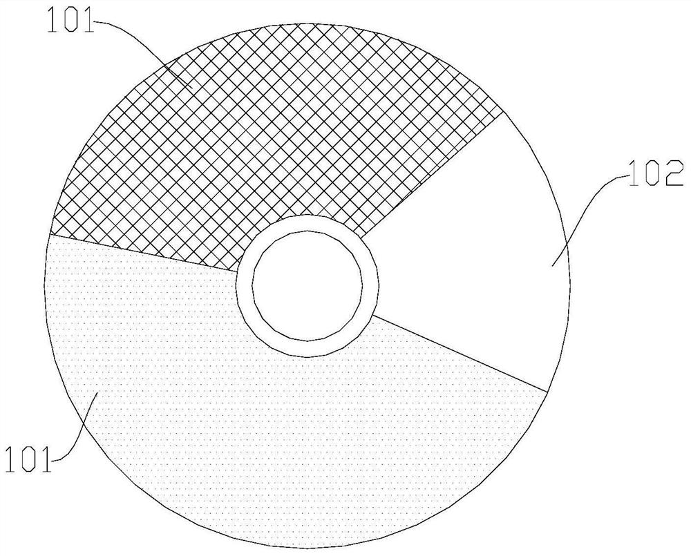
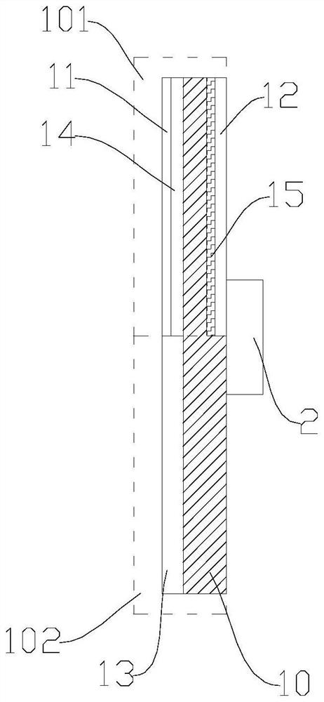
[0043] Specifically, such as figure 1 and figure 2 As shown, in the embodiment of the (reflective) wavelength conversion component 1 provided by the present invention, the substrate 10 is configured as a disk-shaped structure, and the fluorescent layer 11 is located on the first plate surface of the substrate 10 .

[0044] Further, the wavelength conversion component 1 has two fan-shaped wavelength conversion regions 101 and a fan-shaped transmission region 102, one of the wavelength conversion regions 101 has a fan-shaped yellow fluorescent layer 11, specifically, the yellow fluorescent layer 11 receives light Excited to generate yellow fluorescence; the other wavelength conversion region 101 has a fan-shaped green fluorescent layer 11, specifically, the green fluorescent layer 11 is excited by the laser to generate green fluorescence. Wherein, in other embodiments, in order to save material, the fluorescent layer 11 may be in a ring structure, wherein the center of the flu...

Embodiment 2

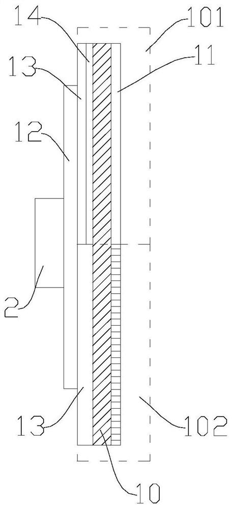
[0057] Specifically, such as figure 1 and image 3 As shown, in the embodiment of the (transmissive) wavelength conversion component 1 provided by the present invention, the substrate 10 is configured as a disk-shaped structure, and the fluorescent layer 11 is located on the first plate surface of the substrate 10 .

[0058] Further, the wavelength conversion component 1 has two fan-shaped wavelength conversion regions 101 and a fan-shaped transmission region 102, one of the wavelength conversion regions 101 has a fan-shaped yellow fluorescent layer 11, specifically, the yellow fluorescent layer 11 receives light Excited to generate yellow fluorescence; another wavelength conversion region 101 of the laser beam has a fan-shaped green fluorescent layer 11, specifically, the green fluorescent layer 11 is excited by the laser to generate green fluorescence. Wherein, in other embodiments, in order to save material, the fluorescent layer 11 may be in a ring structure, wherein the ...

Embodiment 3

[0070] like Figure 4 As shown, in this embodiment, the wavelength conversion component 1 is the (reflective) wavelength conversion component 1 of the first embodiment. Figure 4 The straight line in the optical path of the figure represents the laser beam, and the dotted line represents the fluorescent light beam (including yellow fluorescent light and green fluorescent light).

[0071] Specifically, the light beam emitted by the laser is blue light (spectral range of 420nm-470nm), which is adjusted to stable parallel light after the lens assembly 3a, and then passes through the dichroic mirror 4a to the lens assembly 3b, and the lens assembly 3b is used for The laser beam is focused and collimated, and the laser beam passes through the lens assembly 3 b and then shoots to the wavelength conversion component 1 .

[0072] When the laser beam hits the transmission area 102, the laser beam passes through the transmission area 102 and shoots to the lens assembly 3c, the lens ass...


PUM

PropertyMeasurementUnit
transmission spectroscopyaaaaaaaaaa
reflectance spectroscopyaaaaaaaaaa
thicknessaaaaaaaaaa

Abstract

Embodiments of the present invention provide a wavelength conversion component and a laser light source, which relate to the technical field of optical equipment and solve the technical problems of thermal reliability and low light conversion efficiency of the wavelength conversion component; the wavelength conversion component includes a substrate, and the substrate includes a transmission region and at least one wavelength conversion region, the wavelength conversion region is cured and molded with a fluorescent layer; wherein, the transmission region is used for transmitting laser light, and the fluorescent layer is used for being excited by the laser light to generate fluorescence. The wavelength conversion component of the present invention adopts the fluorescent layer to be directly cured and formed on the wavelength conversion region, thereby avoiding the intervention of other connecting media, thereby retaining the high heat resistance of the fluorescent layer to the greatest extent, and at the same time, because the fluorescent layer and the substrate The tight fit ensures the heat exchange efficiency between the fluorescent layer and the substrate to be greatly guaranteed; thereby ensuring the thermal stability and light conversion efficiency of the wavelength conversion component.

Description

technical field [0001] The invention relates to the technical field of optical equipment, in particular to a wavelength conversion component and a laser light source. Background technique [0002] Lasers are widely used in projection display devices because of their advantages of high brightness, strong monochromaticity, and wide color gamut. Nowadays, the size of projection displays is getting larger and larger, and the requirements for output energy of light sources are also getting higher and higher. [0003] At present, laser light sources widely use high-energy lasers to excite phosphors to emit light; the wavelength conversion components in the prior art are mainly fluorescent wheels, which include circular substrates, phosphors are fixed on the substrates through carriers, and laser beams are irradiated on the phosphors to realize light emission. In general, the fixation methods between the phosphor powder and the substrate can be roughly divided into two types: [0...

Claims


Application Information

Patent Timeline
Patent Type & Authority Patents(China)
IPC IPC(8): G03B21/20
CPCG03B21/204G03B21/2066G03B21/2013G03B21/206
Inventor 张勇高迪
Owner QINGDAO HISENSE LASER DISPLAY CO LTD
Learn More