
Cloth positioner for continuous processing

a positioner and cloth technology, applied in the direction of auxillary welding devices, cloth making devices, soldering devices, etc., can solve the problem of giving higher offset error values, achieve the effect of increasing the yield factor of finished products, reducing the cost of fixtures and waste of resources, and increasing industrial competitiveness

Active Publication Date: 2018-04-26
WHOLEKNIT INT CO LTD
View PDF4 Cites 2 Cited by
  • Summary
  • Abstract
  • Description
  • Claims
  • Application Information

AI Technical Summary

Benefits of technology

The patent describes a cloth positioner that can be used repeatedly in different processing procedures to increase processing precision and yield, overcoming the barrier of automated processing. The positioner can be easily adjusted and used without the need for constant re-positioning, resulting in increased productivity and efficiency. Additionally, the reuse of the positioner leads to decreased costs and waste, making it more competitive in the market.

Problems solved by technology

However, once the cloth is re-positioned, one more offset error value is given; namely, the cloth has different portions that originally apply different forces of tension, so once the cloth is processed in one processing procedure, such as ironing or thermo-compression, the cloth has an irregular outer profile.
Thus, when the cloth is re-located on a different holding pattern die one more time for a next processing procedure, such as printing and dyeing or cutting, the cloth must be re-positioned, thereby a higher offset error value being given.

Method used


Image

  • Cloth positioner for continuous processing
  • Cloth positioner for continuous processing
  • Cloth positioner for continuous processing

Examples


Embodiment Construction

[0023]The following descriptions are exemplary embodiments only, and are not intended to limit the scope, applicability or configuration of the invention in any way. Rather, the following description provides a convenient illustration for implementing exemplary embodiments of the invention. Various changes to the described embodiments may be made in the function and arrangement of the elements described without departing from the scope of the invention as set forth in the appended claims.

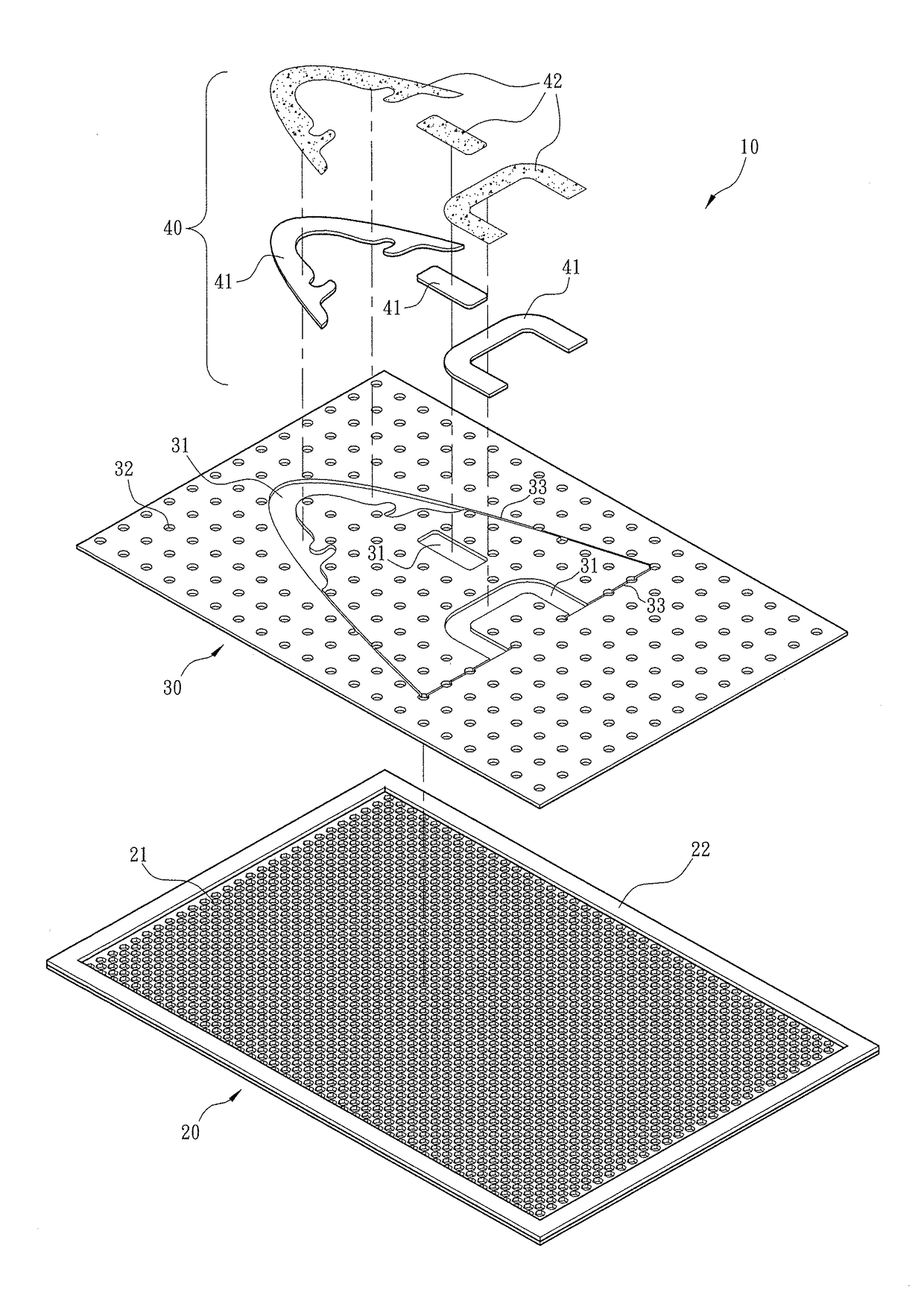
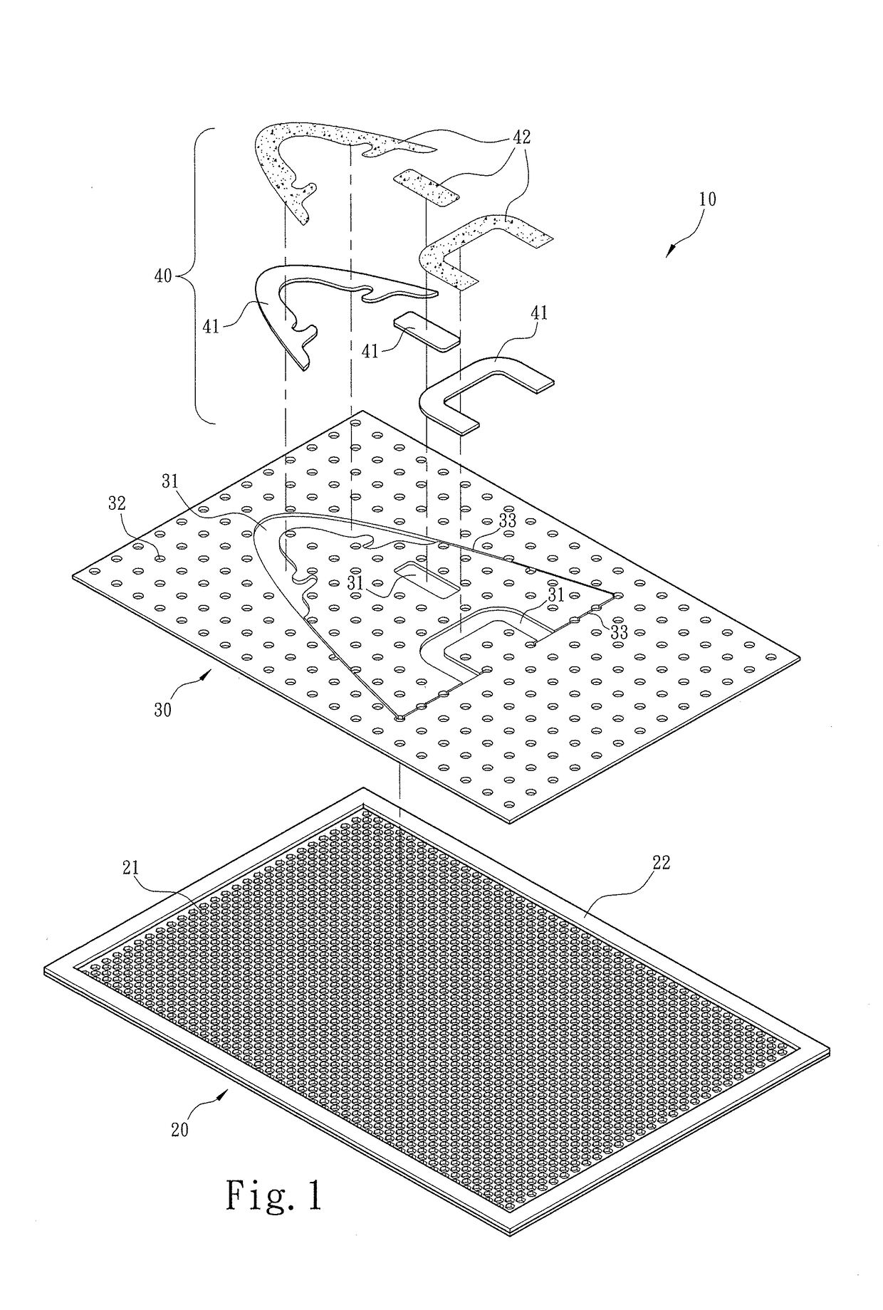
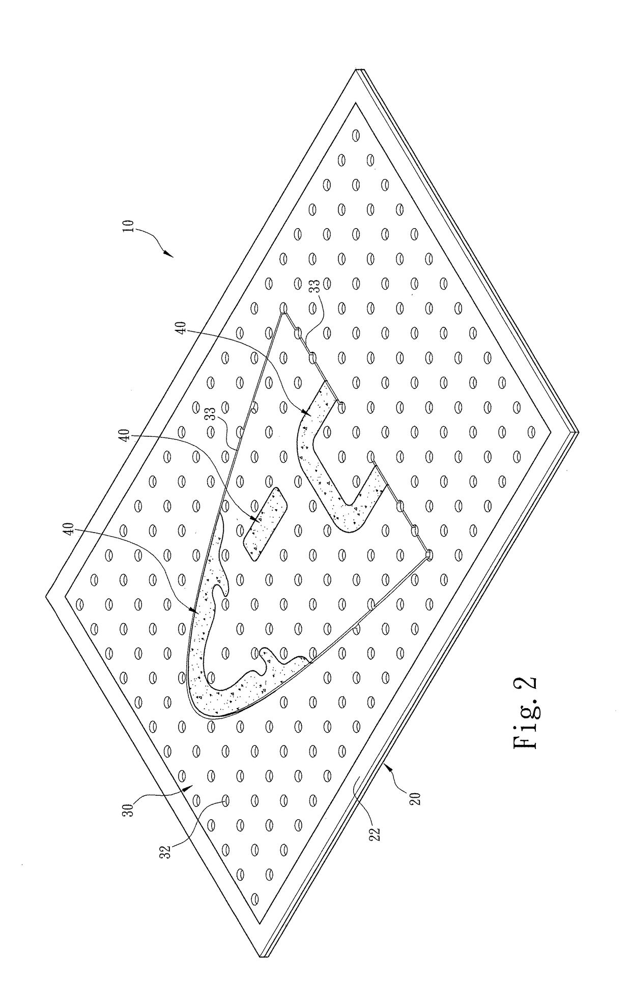
[0024]In order to further know the features and technical means of a cloth positioner for continuous processing according to this invention, refer to preferred embodiments and detailed description according to this invention accompanied with drawings. Firstly, refer to FIGS. 1 through 3 and FIGS. 7 and 8 that illustrate respectively schematic exploded and assembly views of the isometric appearance of the cloth positioner in which a figure position abutment pin piece is positioned in and fixed to the...


PUM

PropertyMeasurementUnit
diameteraaaaaaaaaa
thicknessaaaaaaaaaa
forces of tensionaaaaaaaaaa

Abstract

A cloth positioner for continuous processing according to this invention includes a processing base, an alignment plate provided on the processing base, and at least one figure position abutment pin piece. The processing base includes a plurality of thru holes. The alignment plate includes at least one pin piece slot matching with the figure position abutment pin piece, a plurality of air pressure vents, and at least one laser cutting line groove. With the figure position abutment pin piece that is provided for fixing a cloth onto the pin piece slot, the cloth is positioned on the cloth positioner for continuous processing.

Description

FIELD OF THE INVENTION[0001]This invention relates to a holding pattern die for processing and particularly to a cloth positioner for continuous processing.BACKGROUND OF THE INVENTION[0002]A so-called cloth is a material that may be made into a garment or upper as a semi-product. The so-called continuous processing is herein a processing procedure, comprising at least an ironing step, a thermo-compression step, a printing and dyeing step, and a cutting step. In an existing technology, before being processed in one of the above processing procedures, the cloth generally needs to be located different holding pattern dies and is re-positioned. However, once the cloth is re-positioned, one more offset error value is given; namely, the cloth has different portions that originally apply different forces of tension, so once the cloth is processed in one processing procedure, such as ironing or thermo-compression, the cloth has an irregular outer profile. Thus, when the cloth is re-located ...

Claims


Application Information

Patent Timeline
Patent Type & Authority Applications(United States)
IPC IPC(8): D06H7/00
CPCD06H7/00A41H15/00B23K37/0408B23K26/38B23K2103/38
Inventor KUO, MING-SHENGLI, YU-LINYANG, CHIEN-HUI
Owner WHOLEKNIT INT CO LTD
Learn More