Touch display panel and drive circuit, electronic apparatus thereof

a drive circuit and display panel technology, applied in the field of touch display technology, can solve the problems of occupying display duration, occurrence of error reading phenomenon, leakage current condition of the resistor, etc., and achieve the effects of enhancing display brightness and display image stability, preventing error reading phenomenon generated, and reducing circuit power consumption

Active Publication Date: 2018-04-26
WUHAN CHINA STAR OPTOELECTRONICS TECH CO LTD
View PDF2 Cites 1 Cited by
  • Summary
  • Abstract
  • Description
  • Claims
  • Application Information

AI Technical Summary

Benefits of technology

[0034]In the present invention, with providing the data line switch between the pixel electrode and the data line drive unit, the objective of disconnecting the pixel electrode and the data line drive unit as the data line drive unit does not output the signal can be achieved. Thus, it prevents the error reading phenomenon generated by the transistor leakage, and reduce the entire power consumption of the circuit to enhance the display brightness and the stability of the display image, and promote the display effect of the touch display panel. The touch display panel and the electronic apparatus of the present invention can prevent the error reading phenomenon generated by the transistor leakage, and reduce the entire power consumption of the circuit, and promote the display effect.

Problems solved by technology

However, the transistor has the condition of leakage current.
Therefore, as scanning and reading the touch signals of the pixel units of one row, the data line may have the possibility to receive the noise signal generated by the leakage current of the other rows to result in the occurrence of the error reading phenomenon.
Besides, the error reading of the touch will occupy the display duration many times to increases the entire power consumption.
Ultimately, it leads to the decrease of the screen brightness, the unstable display image and the display effect decrease.

Method used


Image

  • Touch display panel and drive circuit, electronic apparatus thereof
  • Touch display panel and drive circuit, electronic apparatus thereof

Examples


Embodiment Construction

[0037]Embodiments of the present invention are described in detail with the technical matters, structural features, achieved objects, and effects with reference to the accompanying drawings as follows. It is clear that the described embodiments are part of embodiments of the present invention, but not all embodiments. Based on the embodiments of the present invention, all other embodiments to those of ordinary skill in the premise of no creative efforts obtained, should be considered within the scope of protection of the present invention.

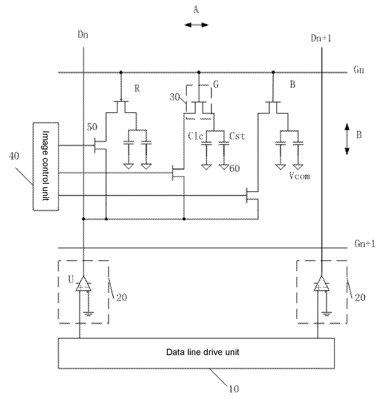
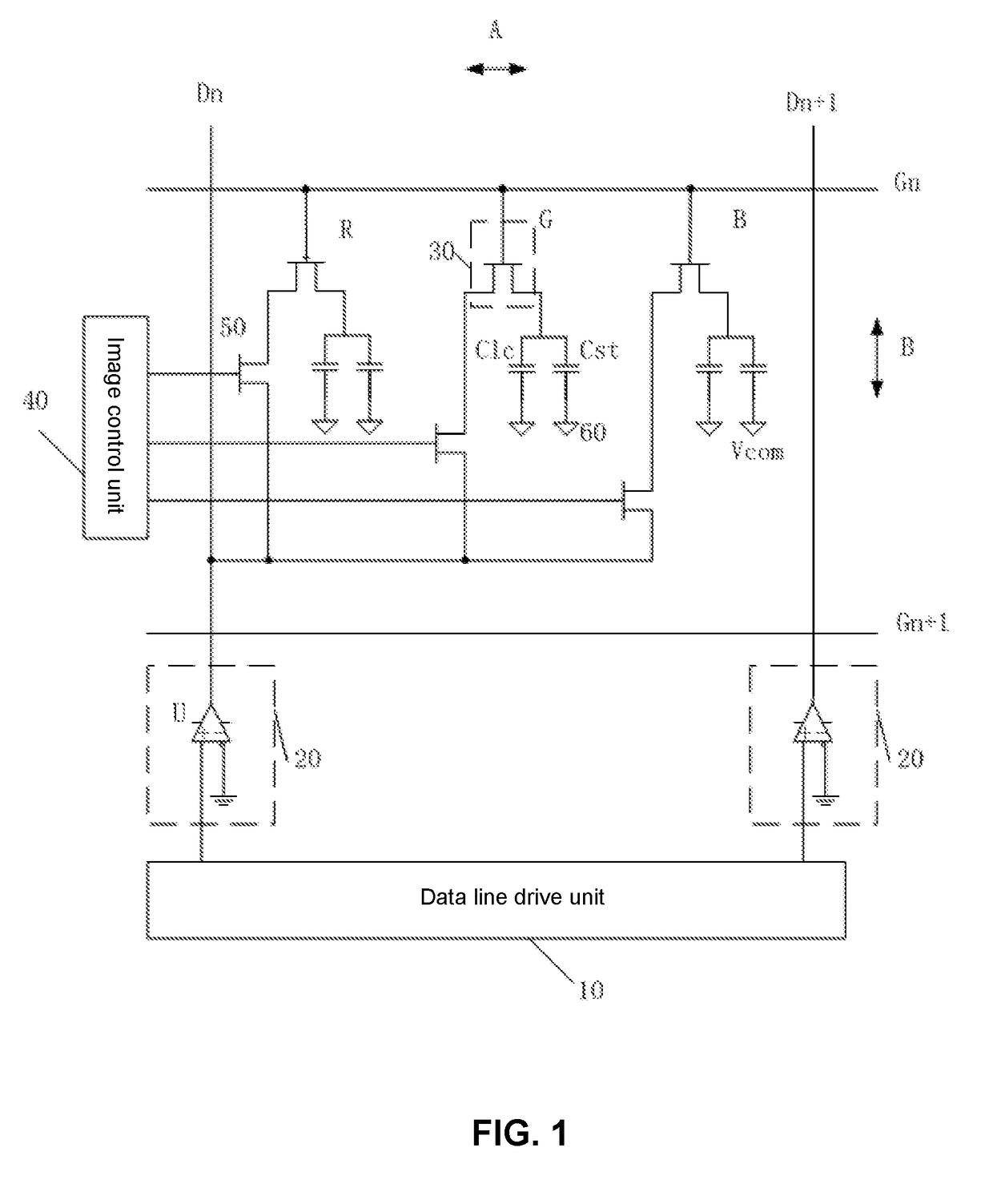
[0038]Please refer to FIG. 1. The touch display panel drive circuit of the present invention comprises a data line drive unit 10, a pixel electrode, a data line switch 20, a plurality of gate lines and a plurality of data lines, and the plurality of gate lines are extended in a first direction A and separately aligned along a second direction B, and the plurality of data lines are extended in the second direction B and separately aligned along the ...


PUM

PropertyMeasurementUnit
light transmittanceaaaaaaaaaa
power consumptionaaaaaaaaaa
brightnessaaaaaaaaaa

Abstract

The touch display panel drive circuit provided by the present invention comprises a data line drive unit, a plurality of gate lines and a plurality of data lines, and a junction of two adjacent gate lines and two adjacent data lines forms a pixel region, and a pixel switch is located inside the pixel region; the touch display panel drive circuit further comprises a data line switch between the data line and the data line drive unit; as the data line drive unit does not output the data signal, an output of the data line switch is a high-impedance state, and the data line drive unit is disconnected with the pixel switch. The present invention can prevent the error reading phenomenon generated by the transistor leakage, and can enhance the display brightness and the stability of the display image, and promote the display effect of the touch display panel.

Description

CROSS REFERENCE[0001]This application claims the priority of Chinese Patent Application No. 201610288584.6, entitled “Touch display panel and drive circuit, electronic apparatus thereof”, filed on May 4, 2016, the disclosure of which is incorporated herein by reference in its entirety.FIELD OF THE INVENTION[0002]The present invention relates to a touch display technology field, and more particularly to a touch display panel and a drive circuit, an electronic apparatus thereof.BACKGROUND OF THE INVENTION[0003]With the population of the smart electronic products, the capacitive touch panel has been widely applied in kinds of electronic products, such as the cellular phone, the tablet and etc. At present, the more common capacitive touch panels are three kinds of OGS (One Glass Solution), On-Cell and In-Cell. The In-Cell has the advantage in manufacture process. In comparison with the OGS and the On-Cell, it has advantages of being thinner, having better light transmittance and possess...

Claims


Application Information

Patent Timeline
Patent Type & Authority Applications(United States)
IPC IPC(8): G06F3/041G02F1/1368G02F1/1333G02F1/1362G09G3/36G06F3/044
CPCG02F1/136286G09G3/3688G09G3/3607G06F3/044G09G2300/0452G02F2201/121G02F2201/123G09G2320/0214G09G2330/023G06F3/0418G02F1/1368G02F1/13338G06F1/3265G09G3/3648G06F3/0412G06F3/04184
Inventor LU, YUCHENGJI, FEILIN
Owner WUHAN CHINA STAR OPTOELECTRONICS TECH CO LTD
Why Eureka
Try Eureka