
Radiation emitting device, method for controlling radiation emitting device, and program

a radiation emitting device and radiation technology, applied in the field of radiation emitting devices, methods for controlling radiation emitting devices, and programs, can solve the problems of reducing the life of the battery, increasing power consumption, and reducing the operating rate, so as to reduce power consumption

Active Publication Date: 2018-05-03
FUJIFILM CORP
View PDF15 Cites 6 Cited by
  • Summary
  • Abstract
  • Description
  • Claims
  • Application Information

AI Technical Summary

Benefits of technology

The invention aims to offer a radiation emitting device, method, and program that can efficiently reduce power consumption. Its technical effect is to provide a solution for reducing energy usage, which is currently a significant issue to be addressed.

Problems solved by technology

However, in the method disclosed in JP1994-217973A (JP-H06-217973A), a collimator that narrows the radiation field is sequentially driven according to the range of the optical image in order to match the radiation field with the range indicated by the acquired optical image, which causes an increase in power consumption.
Therefore, in a case in which power consumption increases, the life of the battery is reduced, which causes a reduction in operating rate.

Method used


Image

  • Radiation emitting device, method for controlling radiation emitting device, and program
  • Radiation emitting device, method for controlling radiation emitting device, and program
  • Radiation emitting device, method for controlling radiation emitting device, and program

Examples


Embodiment Construction

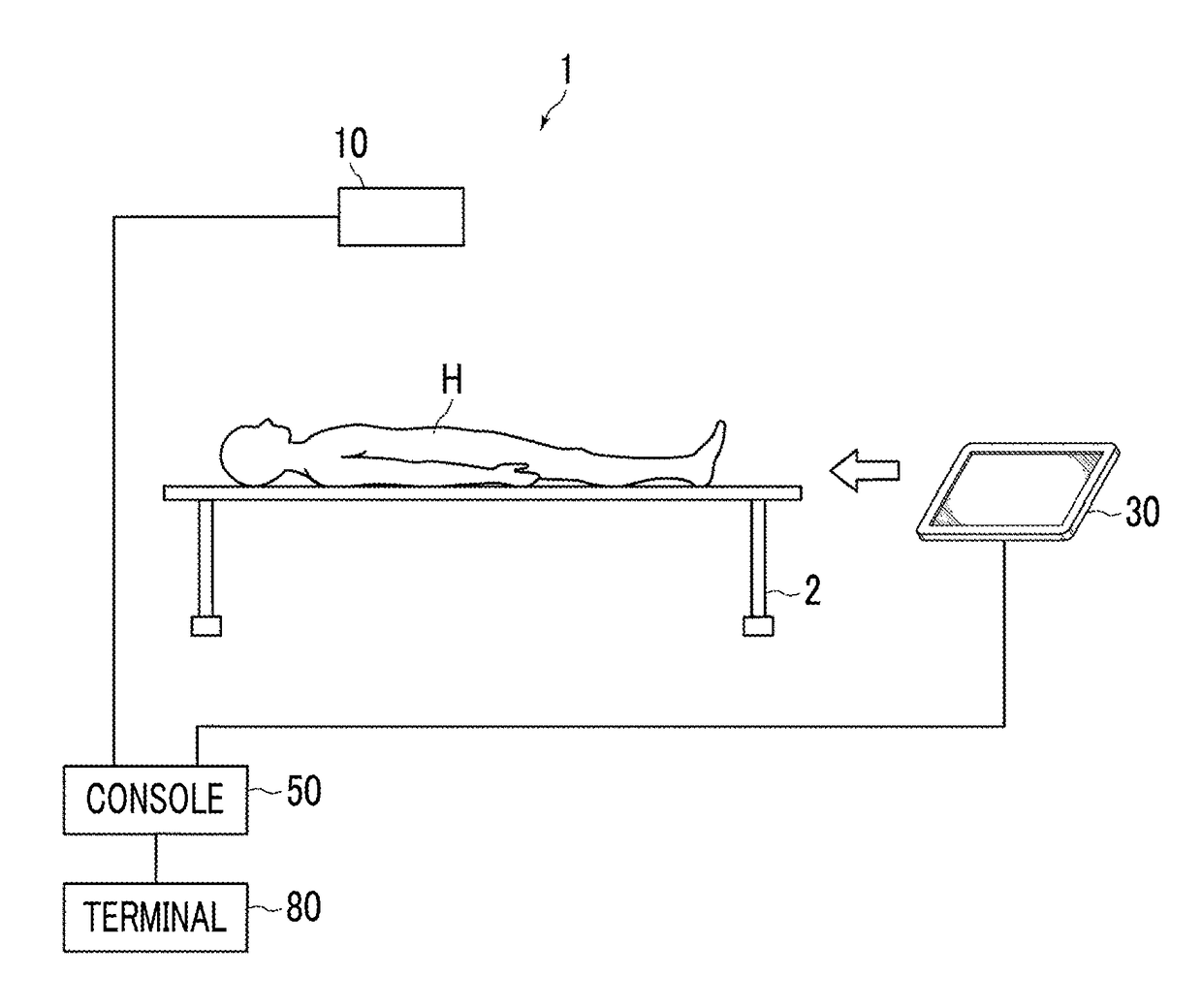
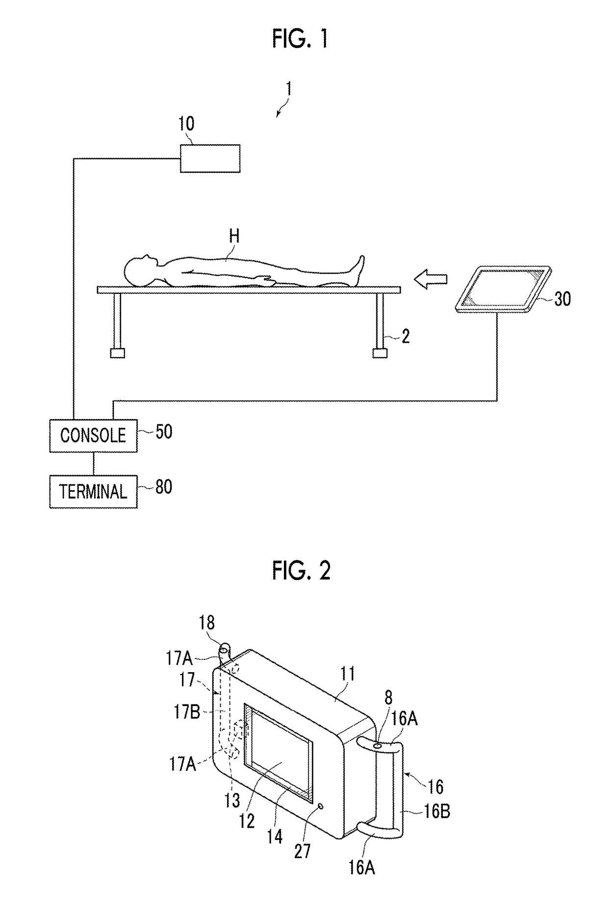
[0036]Hereinafter, embodiments of the invention will be described with reference to the drawings. FIG. 1 is a diagram schematically illustrating a radiography apparatus according to an embodiment of the invention. As illustrated in FIG. 1, a radiography apparatus 1 according to this embodiment includes a portable radiation emitting device 10, a radiation detector 30, and a console 50. For example, in order to acquire a radiographic image of a subject H that lies on a bed 2, the radiation detector 30 is inserted between the subject H and the bed 2, the subject H is irradiated with radiation emitted from the portable radiation emitting device 10, and a radiographic image of the subject H is acquired by the radiation detector 30. In addition, the console 50 is connected to a terminal 80 of, for example, a doctor through a network.

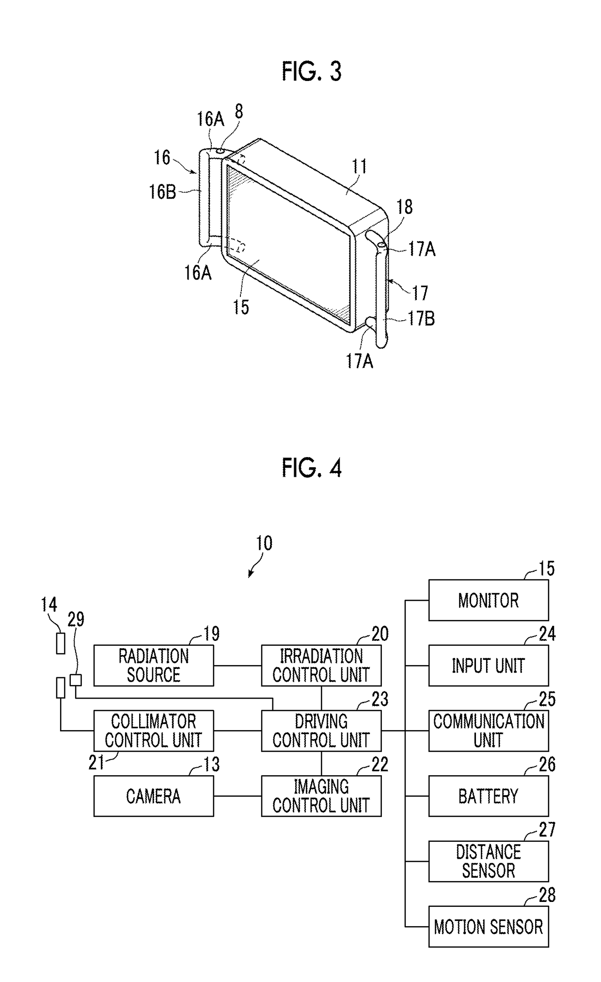
[0037]FIG. 2 is a front perspective view illustrating the radiation emitting device 10. FIG. 3 is a rear perspective view illustrating the radiation emitting ...


PUM


Abstract

Provided are a radiation emitting device forming a radiography apparatus, a method for controlling the radiation emitting device, and a program which can reduce power consumption. A radiation emitting device includes a radiation source, a collimator that sets a radiation field region, imaging unit for capturing an image of an imaging target, a display unit that displays the image captured by the imaging unit, an exposure switch, and a control unit that issues a collimator driving command to direct the collimator to set the radiation field region determined from the captured image to the collimator in a case in which the exposure switch is operated.

Description

CROSS-REFERENCE TO RELATED APPLICATIONS[0001]This application is a continuation application of International Application No. PCT / JP2016 / 002888 filed Jun. 15, 2016, the disclosure of which is incorporated herein by reference in its entirety. Further, this application claims priority from Japanese Patent Application No. 2015-124512, filed Jun. 22, 2015, the disclosure of which is incorporated herein by reference in its entirety.BACKGROUND OF THE INVENTION1. Field of the Invention[0002]The present invention relates to a radiation emitting device for capturing a radiographic image, a method for controlling the radiation emitting device, and a computer-readable storage medium.2. Description of the Related Art[0003]For example, as disclosed in JP2012-29889A and Toshiba Medical Supply Co., Ltd., Radiography Apparatus IPF-21, [online], [Searched on Jul. 30, 1999], Internet <URL: http: / / www.toshiba-iryouyouhin.co.jp / tmeds / xrays / ipf21.html>, a portable radiation emitting device has been...

Claims


Application Information

Patent Timeline
IPC IPC(8): A61B6/00A61B6/06
CPCA61B6/542A61B6/06A61B6/40A61B6/461A61B6/08A61B6/4233A61B6/548A61B6/547A61B6/544A61B6/587A61B6/488H05G1/64H05G1/00A61B6/00
Inventor INOUE, TOMOKIOHTA, YASUNORIOGURA, RYOSUKEAOSHIMA, YUZONARIYUKI, FUMITOMATSUURA, MASAYOSHINAKATSUGAWA, HARUYASU
Owner FUJIFILM CORP
Learn More