Robot system

a robot and robot technology, applied in the field of robot systems, can solve problems such as difficulty in increasing throughput, and achieve the effect of accurately performing the holding and releasing of objects by the robot and accurately calculating the teaching points

Inactive Publication Date: 2018-05-03
SEIKO EPSON CORP
View PDF3 Cites 9 Cited by
  • Summary
  • Abstract
  • Description
  • Claims
  • Application Information

AI Technical Summary

Benefits of technology

[0038]With this configuration, it is possible to highly accurately calculate the teaching points. Since the robot performs the holding and the release of the object using the teaching points, it is possible to reduce or prevent, for example, holding mistakes of the objects. Therefore, it is possible to accurately perform the holding and the release of the objects by the robot.

Problems solved by technology

Therefore, in the test handler module, it is difficult to increase a throughput.

Method used


Image

  • Robot system
  • Robot system
  • Robot system

Examples


first embodiment

1. Configuration of a Robot System

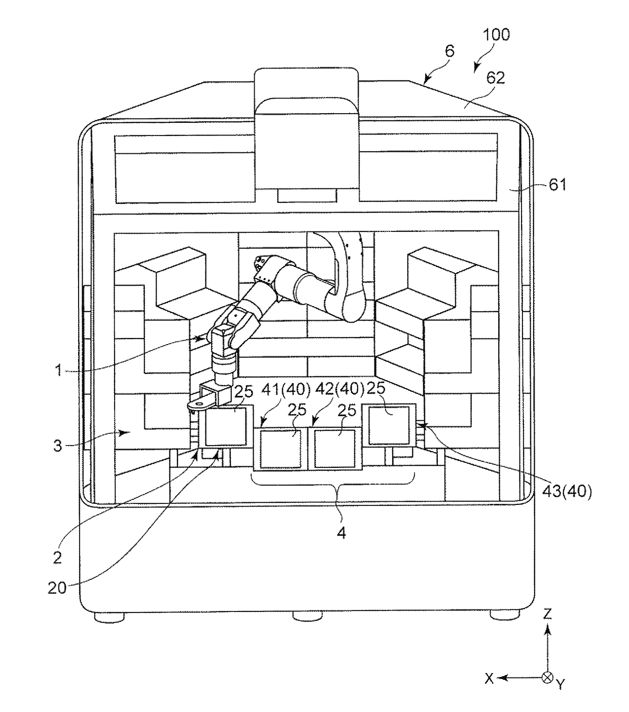
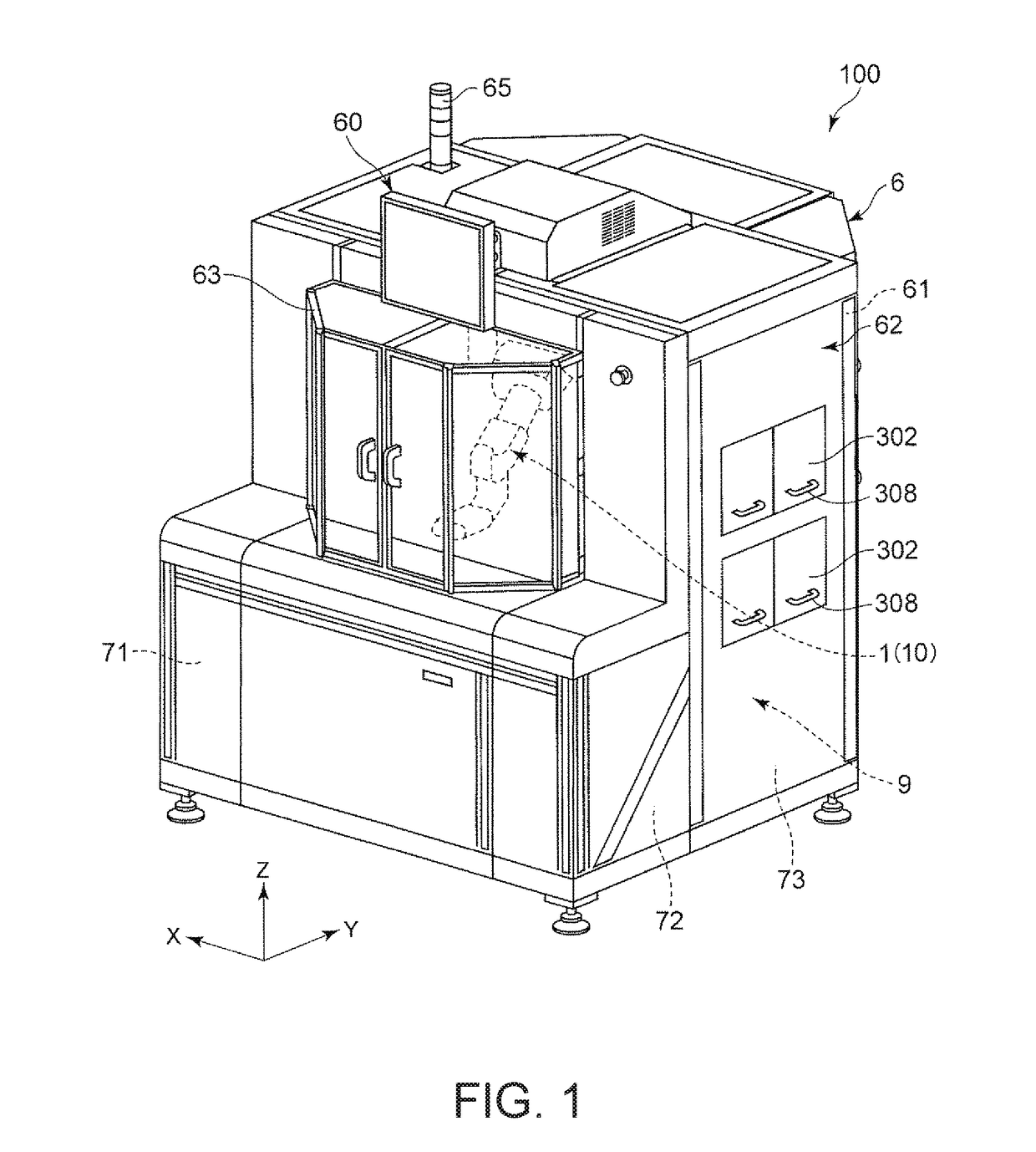
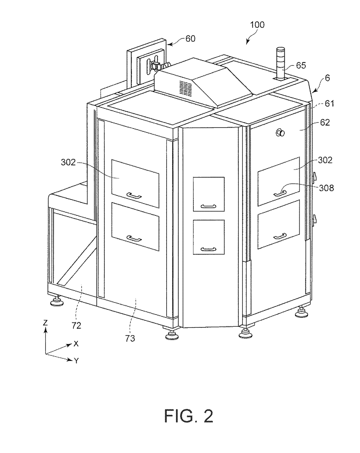
[0100]FIG. 1 is a perspective view of a robot system according to a first embodiment of the invention viewed from the front side. FIG. 2 is a perspective view of the robot system shown in FIG. 1 viewed from the back side. FIG. 3 is a left side view of the robot system shown in FIG. 1. FIG. 4 is a perspective view showing the inside of the robot system shown in FIG. 1. FIG. 5 is a plan view showing the inside of the robot system shown in FIG. 1. FIG. 6 is a block diagram of the robot system shown in FIG. 1. FIG. 7 is a plan view showing a placing member included in a supply section shown in FIG. 1. FIG. 8 is a perspective view showing a test unit shown in FIG. 1. FIG. 9 is a side view of a test section shown in FIG. 1. FIG. 10 is a plan view of a test table shown in FIG. 8. FIG. 11 is a diagram showing a state in which the test table shown in FIG. 8 is drawn out to the outside of a housing. Note that, in FIG. 7, illustration of a socket 307 included ...

second embodiment

[0320]A second embodiment of the invention is explained.

[0321]FIG. 46 is a side view showing a test section included in a robot system according to the second embodiment of the invention. FIG. 47 is a diagram showing an example of an object tested in the test section shown in FIG. 46.

[0322]The robot system according to this embodiment is the same as the robot system in the first embodiment except that the configuration of the test section is different. Note that, in the following explanation, concerning the second embodiment, differences from the first embodiment are mainly explained. Explanation of similarities is omitted.

[0323]The test section 300 in this embodiment includes, as shown in FIG. 46, a socket 309 including a concave section 3091 functioning as an insertion section into which the object 80 can be inserted. The concave section 3091 is opened to the right side in FIG. 46. The socket 309 is formed in, for example, a flat shape and is suitable for a test of an object, a te...

third embodiment

[0325]A third embodiment of the invention is explained.

[0326]FIG. 48 is a schematic diagram of the inside of a robot system according to the third embodiment of the invention viewed from the upper side.

[0327]The robot system according to this embodiment is the same as the robot systems in the embodiments explained above except that the configuration of a test section is different. Note that, in the following explanation, concerning the third embodiment, differences from the embodiments explained above are mainly explained. Explanation of similarities is omitted.

[0328]The test unit 3 in this embodiment includes eight test sections 300. Specifically, the first test section group 31 includes two first test sections 310 (test sections 300), the second test section group 32 includes two second test sections 320 (test sections 300), the third test section group 33 includes two third test sections 330 (test sections 300), and the fourth test section group 34 includes two fourth test sectio...


PUM


Abstract

A robot system includes a supply section configured to supply an object, a first test section group including a plurality of first test sections configured to test the supplied object, a second test section group including a plurality of second test sections configured to test the supplied object, a collecting section configured to collect the tested object, and a robot including a robot arm and configured to hold, convey, and release the object. The robot is capable of collectively conveying a plurality of the objects. A total of conveyance times for the conveyance of the object by the robot from the supply to the collection of the object is shorter than a total of processing times for the holding and the release of the object by the robot.

Description

BACKGROUND1. Technical Field[0001]The present invention relates to a robot system.2. Related Art[0002]There has been known a test handler for testing an electric characteristic of an electronic component.[0003]As such a test handler, for example, JP-A-2013-219354 (Patent Literature 1) discloses a test handler module including a supply conveyor that conveys a substrate, a test chamber in which a test of the substrate conveyed from the supply conveyor is performed, and a discharge conveyor that conveys the substrate for which the test is completed. The test handler module further includes a conveyance robot that receives the substrate from the supply conveyor and conveys the substrate to the test chamber. The conveyance robot performs work for receiving the substrate from the test chamber and delivering the substrate to the discharge conveyor.[0004]However, in the test handler module described in Patent Literature 1, the conveyance robot can convey only one object at a time. Therefore...

Claims


Application Information

Patent Timeline
Patent Type & Authority Applications(United States)
IPC IPC(8): B25J9/16G01R31/28B25J13/08B25J15/06B25J21/00
CPCB25J9/1679G01R31/2893B25J13/085B25J13/086B25J15/0616B25J21/00G01R31/2808B25J15/0052B25J9/0018
Inventor YOKOTA, MASATOKUMAGAI, TOMOHIROKOTANI, NORIAKI
Owner SEIKO EPSON CORP
Why Eureka
Try Eureka