Systems and methods for scour monitoring with fiber optic sensors

a fiber optic sensor and fiber optic technology, applied in the field ofscour monitoring, can solve the problems of compromising the integrity of the structure, compromitting the structural integrity, and unwanted exposure of the structure to flowing water

Active Publication Date: 2018-05-03
UNIV HOUSTON SYST
View PDF0 Cites 5 Cited by
  • Summary
  • Abstract
  • Description
  • Claims
  • Application Information

AI Technical Summary

Benefits of technology

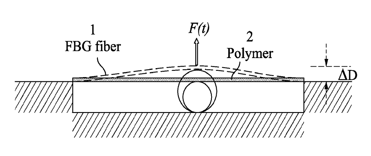
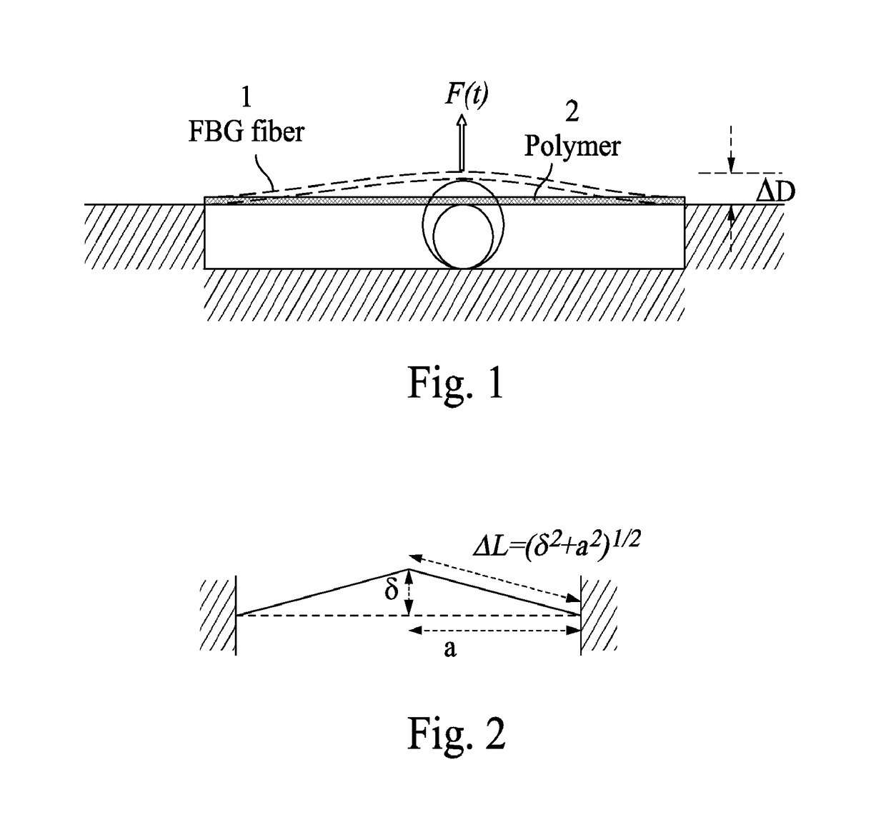
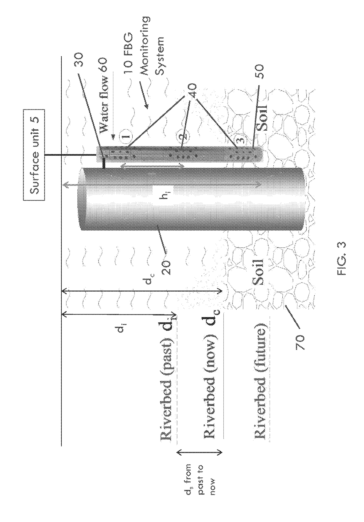
[0008]In one embodiment, a scour monitoring system may provide a housing that is separated into multiple segments that are fluidically isolated from each other. Each segment may provide one or more openings that allow fluid to enter the sensor chamber when soil does not cover the segment or when the soil is scoured away from the segment. The scour monitoring system may be position adjacent to a structure to be monitored for bridge scouring. Each of the segments may provide a water-swellable material positioned near or in contact with a fiber Bragg grating (FBG) cable. If water penetrates a segment, the water-swellable material may expand to deform the FBG cable. The wavelength of the FBG cable may be monitored periodically for changes, thereby providing moisture detection when a change in wavelength is detected.

Problems solved by technology

This removal of surrounding sand, soil, rock, or gravel around a structure, such as bridge pier, may compromise the structural integrity and unwantedly expose the structuring to flowing water.
For example, bridge scour around bridge abutments or piers can compromise the integrity of the structure, and is one of the most common causes of highway bridge failure in the United States (e.g. ˜60% of bridge failures).
The flow of water around an abutment may cause general scour, contraction scour, and / or local scour.
Water normally flows faster around piers and abutments making them susceptible to local scour.
However, these methods require complex computations, expensive equipment, etc.

Method used


Image

  • Systems and methods for scour monitoring with fiber optic sensors
  • Systems and methods for scour monitoring with fiber optic sensors
  • Systems and methods for scour monitoring with fiber optic sensors

Examples


experimental example

[0077

[0078]The following examples are included to demonstrate particular aspects of the present disclosure. It should be appreciated by those of ordinary skill in the art that the methods described in the examples that follow merely represent illustrative embodiments of the disclosure. Those of ordinary skill in the art should, in light of the present disclosure, appreciate that many changes can be made in the specific embodiments described and still obtain a like or similar result without departing from the spirit and scope of the present disclosure.

[0079]Fabricated Prototype

[0080]A prototype of the sensing system was designed and fabricated in the laboratory. FIGS. 10A-10B show the fabricated prototype with three standard units connected by two adjustable units, where the closed assembled view is shown in FIG. 10A and the sensor system with standard unit covers opened shown in FIG. 10B. The standard unit was 100 mm long and the adjustable unit was 100-150 mm long, where each adjus...


PUM

PropertyMeasurementUnit
humidityaaaaaaaaaa
tensionaaaaaaaaaa
flexibleaaaaaaaaaa

Abstract

A scour monitoring system may provide a housing that is separated into multiple segments that are fluidically isolated from each other. The scour monitoring system may be position adjacent to a structure to be monitored for bridge scouring. Each of the segments may provide a water-swellable material positioned near or in contact with a fiber Bragg grating (FBG) cable. If water penetrates a segment, the water-swellable material may expand to deform the FBG cable. The wavelength of the FBG cable may be monitored periodically for changes, thereby providing moisture detection when a change in wavelength is detected.

Description

RELATED APPLICATIONS[0001]This application claims the benefit of U.S. Provisional Patent Application No. 62 / 166,476 filed on May 26, 2015, which is incorporated herein by reference.FIELD OF THE INVENTION[0002]This invention relates to scour monitoring. More particularly, to scour monitoring utilizing a fiber optic sensors.BACKGROUND OF INVENTION[0003]Scour is the result of the erosive action of flowing water, which excavates and carries away sediment, such as sand, soil, rock, and / or gravel, from a structure. This removal of surrounding sand, soil, rock, or gravel around a structure, such as bridge pier, may compromise the structural integrity and unwantedly expose the structuring to flowing water. For example, bridge scour around bridge abutments or piers can compromise the integrity of the structure, and is one of the most common causes of highway bridge failure in the United States (e.g. ˜60% of bridge failures).[0004]The flow of water around an abutment may cause general scour, ...

Claims


Application Information

Patent Timeline
Patent Type & Authority Applications(United States)
IPC IPC(8): G01M3/14G01M3/38G01N21/77
CPCG01M3/141G01M3/38G01N21/774G01N2021/7723G02B6/0208G02B6/02209G01M3/12G01N21/7703
Inventor SONG, GANGBINGKONG, XUANHO, SIU CHUN MICHAEL
Owner UNIV HOUSTON SYST
Why Eureka
Try Eureka