Method and device for recognizing a short circuit in a pwn driver circuit

a driver circuit and short circuit technology, applied in short-circuit testing, power conversion systems, power supply testing, etc., can solve problems such as difficulty in carrying out an evaluation via a simple voltage measuremen

Inactive Publication Date: 2015-08-13
ROBERT BOSCH GMBH
View PDF3 Cites 1 Cited by
  • Summary
  • Abstract
  • Description
  • Claims
  • Application Information

AI Technical Summary

Benefits of technology

[0023]The approach presented here also provides a device which is configured for carrying out, controlling, or implementing the steps of one variant of a method provided here in appro

Problems solved by technology

Since in a pulse width modulation (PWM), both switching states may correspond to a short circuit as well

Method used


Image

  • Method and device for recognizing a short circuit in a pwn driver circuit
  • Method and device for recognizing a short circuit in a pwn driver circuit
  • Method and device for recognizing a short circuit in a pwn driver circuit

Examples


Embodiment Construction

[0034]In the following description of advantageous exemplary embodiments of the present invention, identical or similar reference numerals are used for the elements having a similar action which are illustrated in the various figures, and a repeated description of these elements is dispensed with.

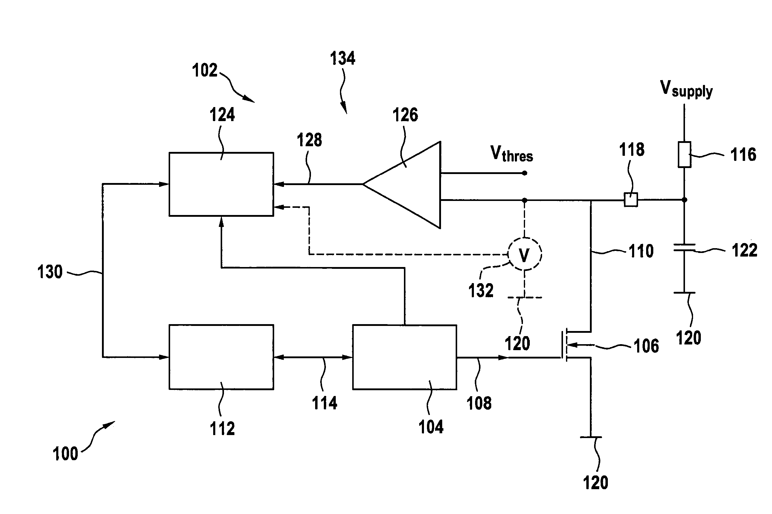
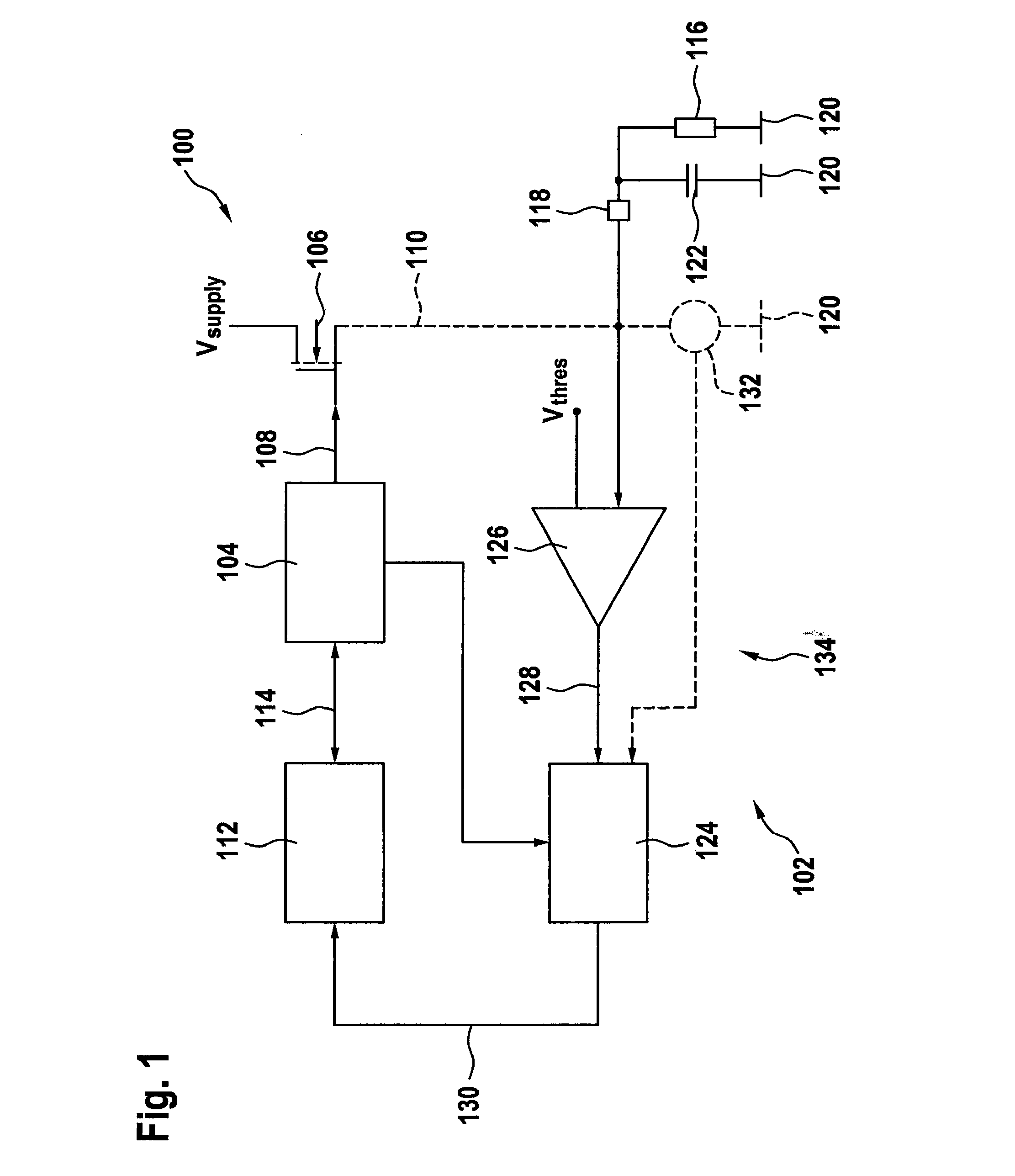
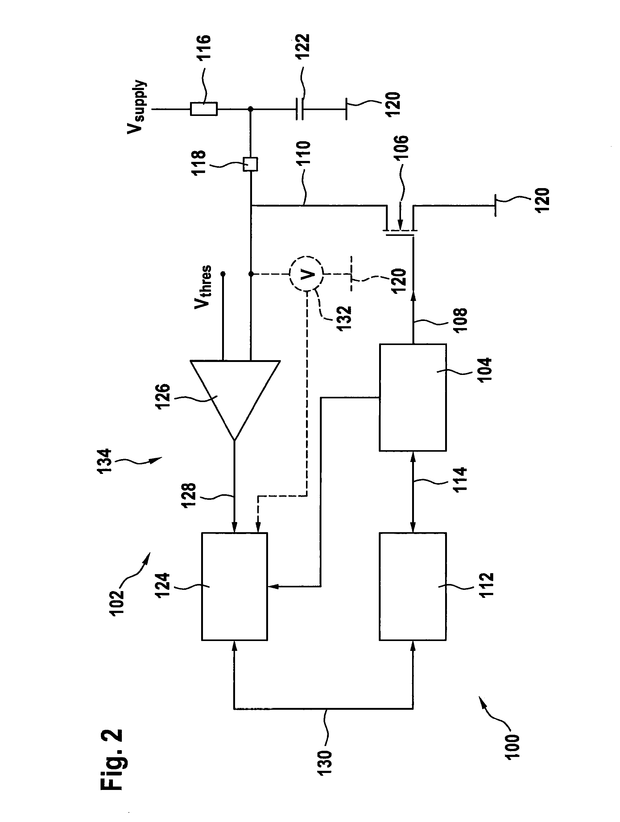
[0035]FIG. 1 shows a block diagram of a PWM driver circuit 100 as a high-side driver together with a monitoring stage 102, according to one exemplary embodiment of the present invention. PWM driver circuit 100 includes a PWM modulator 104 and a power stage unit 106. At an output, PWM modulator 104 provides a control signal 108 which is present at an input of power stage unit 106. A supply voltage Vsupply is present at a terminal of power stage unit 106. An output signal 110 is present at a further terminal of power stage unit 106. PWM modulator 104 is connected to a control unit 112. Control unit 112 provides a control signal 114 for PWM modulator 104. A duty factor or a pulse width of cont...


PUM


Abstract

A method for recognizing a short circuit in a PWM driver circuit, the PWM driver circuit including a PWM modulator and a power stage unit, and the power stage unit provides an output signal using a control signal which is provided by the PWM modulator. The method includes analyzing a voltage value of the output signal in response to a change in the signal level of the control signal and/or a point in time of the change in the signal level. The analyzing also takes place using a predefined threshold value for assessing the voltage value to recognize a short circuit.

Description

RELATED APPLICATION INFORMATION[0001]The present application claims priority to and the benefit of German patent application no. 10 2014 202 678.4, which was filed in Germany on Feb. 13, 2014, the disclosure of which is incorporated herein by reference.FIELD OF THE INVENTION[0002]The present invention relates to a method for recognizing a short circuit in a PWM driver circuit, a corresponding device for recognizing a short circuit in a PWM driver circuit, and a corresponding computer program product.BACKGROUND INFORMATION[0003]A pulse width modulation is frequently used instead of a linear control in order to control the power in consumers. Less power loss is thus converted in the power section, since the power is set by the ratio of the current flow time to the idle time. The output driver is switched only between the “on” and “off” states. It is important to recognize this state in order to protect the PWM controller from an overload due to an external short circuit. Since in a pu...

Claims


Application Information

Patent Timeline
IPC IPC(8): H02H9/02
CPCH02H9/02G01R31/40G01R31/52H02H7/12H02M1/32
Inventor SIEMSS, MATTHIASKARNER, RUEDIGER
Owner ROBERT BOSCH GMBH
Why Eureka
Try Eureka