Current sensor

a current sensor and sensor chip technology, applied in the field of current sensors, can solve the problems of difference in output (sensor chip output) of the two magnetoelectric transducers, the uniform range of the magnetic field decreases in a gap, etc., and achieves the effect of improving the accuracy of anomaly detection and simple circui

Inactive Publication Date: 2018-05-03
TOYOTA JIDOSHA KK
View PDF3 Cites 4 Cited by
  • Summary
  • Abstract
  • Description
  • Claims
  • Application Information

AI Technical Summary

Benefits of technology

[0010]It is preferable that the current sensor disclosed in the present specification may further include a sensor controller. The sensor controller may be configured to output an error signal (a signal indicating anomaly that occurs in at least one of the sensor chips) when an output difference between the two magnetoelectric transducers exceeds a predetermined threshold value. The current sensor described above has a small output difference between the two sensor chips in normal time, so that the predetermined threshold value can be reduced to improve accuracy of anomaly detection.
[0011]The two sensor chips may be disposed such that when the two sensor chips output positive values for a magnetic flux passing the gap respectively, a magnetic induction direction of one of the two sensor chips is opposite to the magnetic induction direction of the other one of the two sensor chips. In that case, outputs of the two respective sensor chips are opposite to each other for positive and negative values. Thus, only simply adding outputs of the two sensor chips together enables an output difference between the two sensor chips (difference in an absolute value of an output value) to be acquired. Then, the sensor controller has a simple circuit.

Problems solved by technology

Unfortunately, when an area of an end face of a magnetism-collecting core is reduced to reduce a sensor in size, a uniform range of a magnetic field decreases in a gap.
As a result, a slight difference in distance between each of two magnetoelectric transducers and the end face center of the magnetism-collecting core causes a difference in magnetic field applied to each of the two magnetoelectric transducers, thereby causing a difference in output (output of sensor chips) of the two magnetoelectric transducers.

Method used


Image

  • Current sensor
  • Current sensor
  • Current sensor

Examples


Embodiment Construction

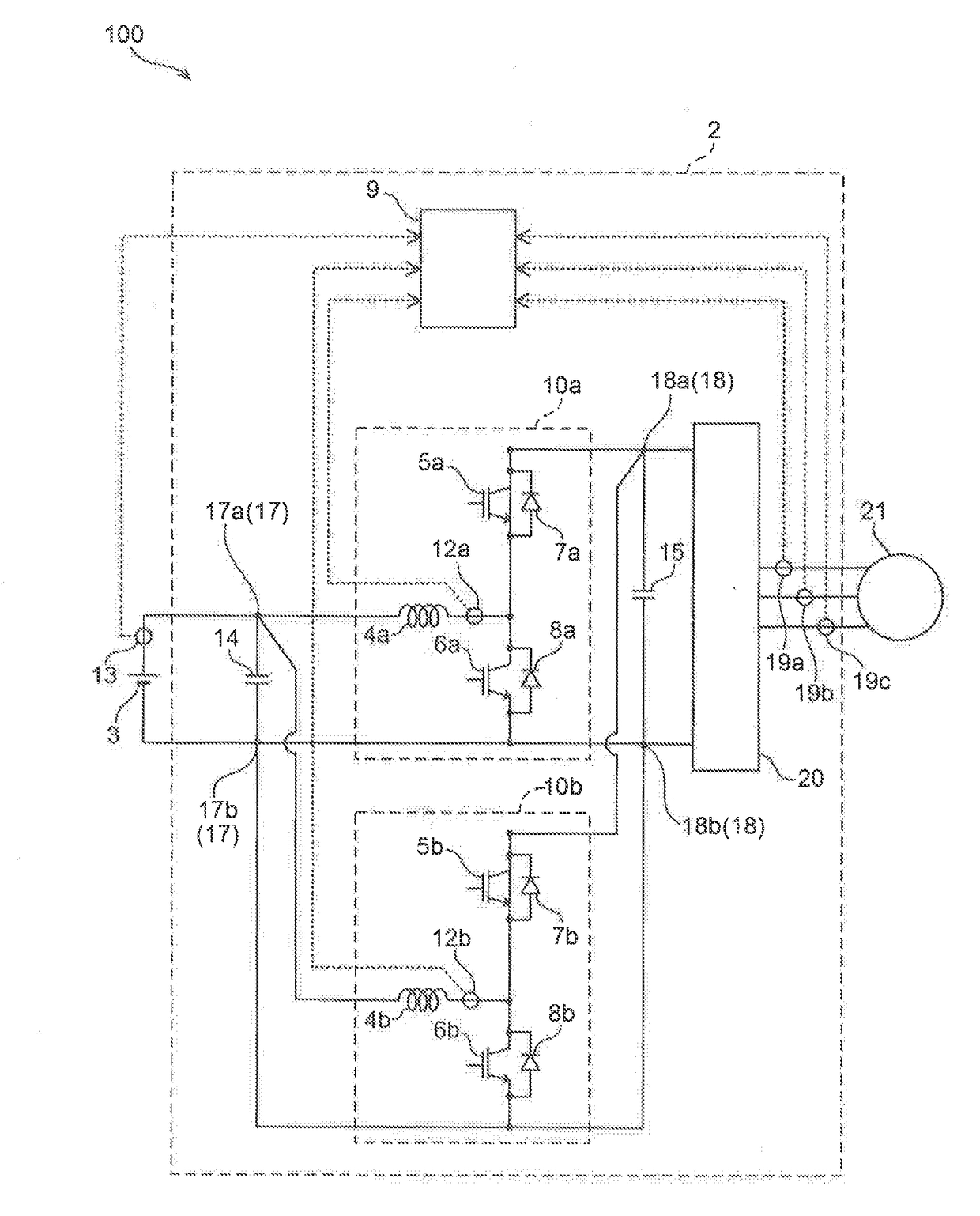
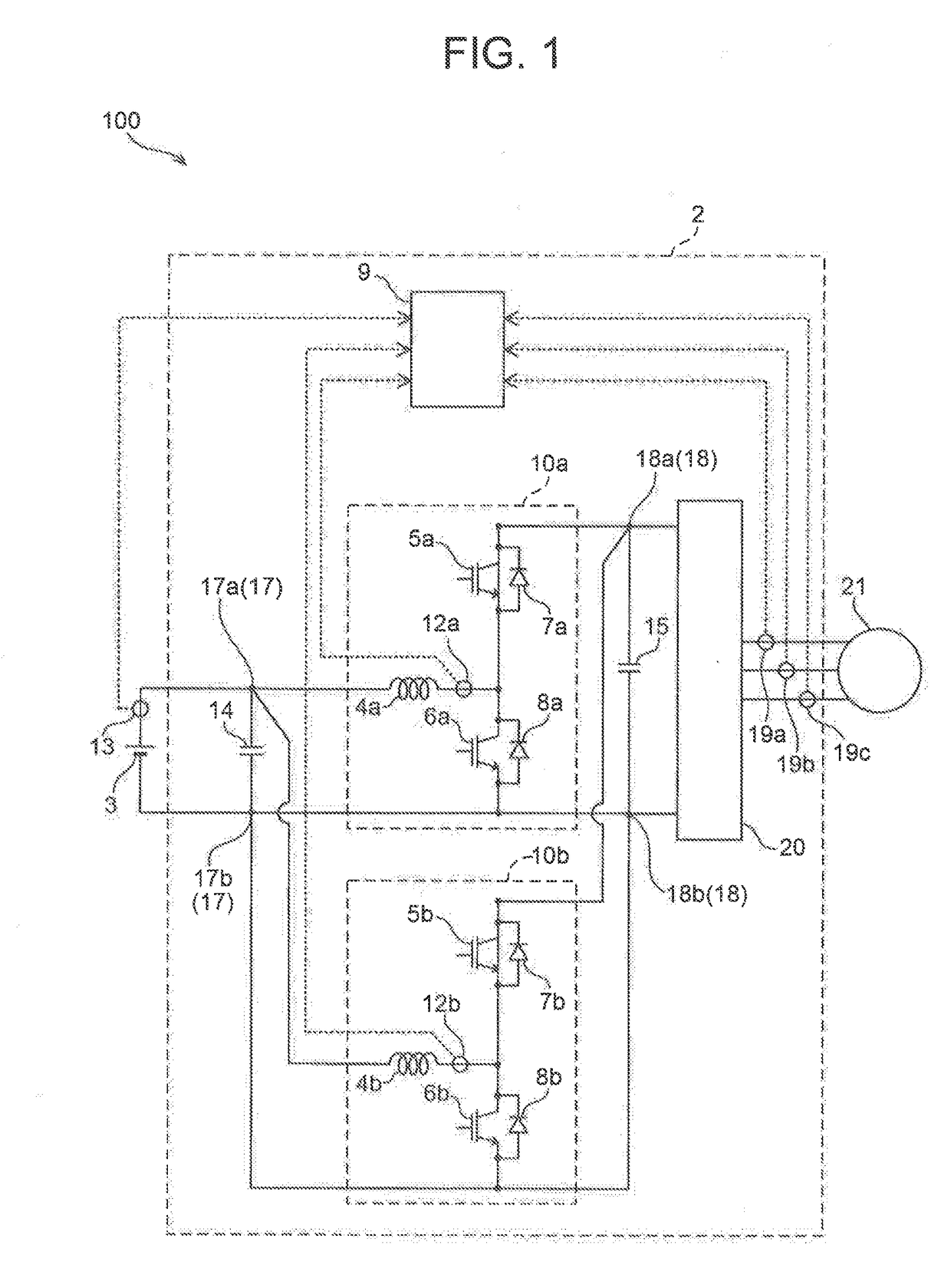
[0025]With reference to drawings, a current sensor of an example will be described. First, an electric vehicle using the current sensor of the example will be described. FIG. 1 is a block diagram of an electric power system of an electric vehicle 100. The electric vehicle 100 travels by driving a motor 21 with electric power of a battery 3. An electric power controller 2 converts a direct current into an alternating current after voltage of DC power of the battery 3 is raised, and supplies the alternating current to the motor 21. When a driver steps a brake, the motor 21 generates power by using deceleration energy of a vehicle. AC power acquired by power generation is converted into a direct current by the electric power controller 2, and is further reduced in voltage to be used for charging the battery 3. The battery 3 includes a current sensor 13.

[0026]The electric power controller 2 includes a pair of voltage converters 10a, 10b, an inverter 20, and two capacitors (a filter capa...


PUM

PropertyMeasurementUnit
currentaaaaaaaaaa
magnetic inductionaaaaaaaaaa
magnetic fluxaaaaaaaaaa

Abstract

Two sensor chips house respective magnetoelectric transducers. The two sensor chips are disposed in the gap. The two sensor chips are disposed such that a magnetic induction direction of each of the two sensor chips is the same as a normal direction of end faces of the magnetism-collecting core, the end faces facing the gap, and the two sensor chips are disposed in an axially symmetric manner to a straight line passing through a center of the gap.

Description

INCORPORATION BY REFERENCE[0001]The disclosure of Japanese Patent Application No. 2016-214590 filed on Nov. 1, 2016 including the specification, drawings and abstract is incorporated herein by reference in its entirety.BACKGROUND1. Technical Field[0002]The present specification discloses a current sensor including a magnetism-collecting core and a magnetoelectric transducer.2. Description of Related Art[0003]There is known a current sensor including a magnetism-collecting core and a magnetoelectric transducer. The magnetism-collecting core is in the shape of a ring surrounding a conductor through which a current flows. The magnetism-collecting core has a gap formed by parting one place of the ring. The magnetoelectric transducer is built in a sensor chip, and the sensor chip is disposed in the gap of the magnetism-collecting core. The sensor chip is disposed such that a magnetic induction direction of the magnetoelectric transducer inside the sensor chip is along a normal direction ...

Claims


Application Information

Patent Timeline
Patent Type & Authority Applications(United States)
IPC IPC(8): G01R15/20G01R15/18G01R19/00H01F38/30
CPCG01R15/202G01R15/183G01R19/0092H01F38/30G01R15/207H01F2038/305G01R19/00
Inventor NAKAYAMA, WATARU
Owner TOYOTA JIDOSHA KK
Why Eureka
Try Eureka