Lidar sensor for detecting an object

Inactive Publication Date: 2018-05-03
ROBERT BOSCH GMBH
View PDF5 Cites 6 Cited by
  • Summary
  • Abstract
  • Description
  • Claims
  • Application Information

AI Technical Summary

Benefits of technology

[0012]The advantage of the present invention is that the electromagnetic radiation may be deflected with the aid of the deflection unit along a predefined direction and emitted by the transmitting unit at a predefined wavelength. One wavelength is assignable to each predefined direction. The wavelength of the emitted electromagnetic radiation may be tuned. The wavelength of the emitted electromagnetic radiation may be adjusted. Such a LIDAR sensor may be simply and cost-effectively implemented. Manufacturing-related fluctuations of the central wavelength of the source, which may amount to as much as 10 nm with normally used laser diodes, for example, may be compensated for by the adjustability of the wavelength. Moreover, the likelihood of a mutual blinding of multiple sensors is significantly reduced, since not only the instantaneous direction, along which the electromagnetic radiation is emitted by the transmitting unit into the sensing region, but also at the same time the wavelength may be sequentially changed.
[0013]In one advantageous embodiment of the present invention, it is provided that the deflection direction corresponds to the transmit filter input direction. The advantage of this embodiment is that the electromagnetic radiation strikes the transmit filter element essentially precisely in a predefined transmit filter input direction. The deflection direction may be adjusted in such a way that the wavelength of emitted electromagnetic radiation may be tuned in a predefined manner. The electromagnetic radiation may be emitted by the transmitting unit in each case at a predefined wavelength along a predefined direction.
[0014]In another advantageous embodiment of the present invention, it is provided that the transmission behavior of the transmit filter element is a function of the transmit filter input direction in such a way that a transmit filter pass range of the transmit filter element changes as a function of the transmit filter input direction. The advantage of this embodiment is that the wavelength of the electromagnetic radiation emitted by the transmitting unit may be tuned.
[0015]In one preferred embodiment of the present invention, it is provided that the deflection unit is orientable in such a way that the electromagnetic radiation emitted by the source strikes the transmit filter element along the tr

Problems solved by technology

Not only is the useful signal detected and measured, however, but also noise from the background radiation.
It may be

Method used


Image

  • Lidar sensor for detecting an object
  • Lidar sensor for detecting an object
  • Lidar sensor for detecting an object

Examples


Embodiment Construction

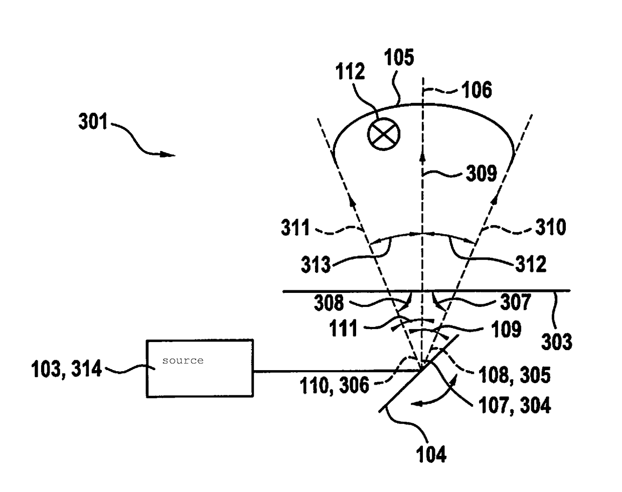
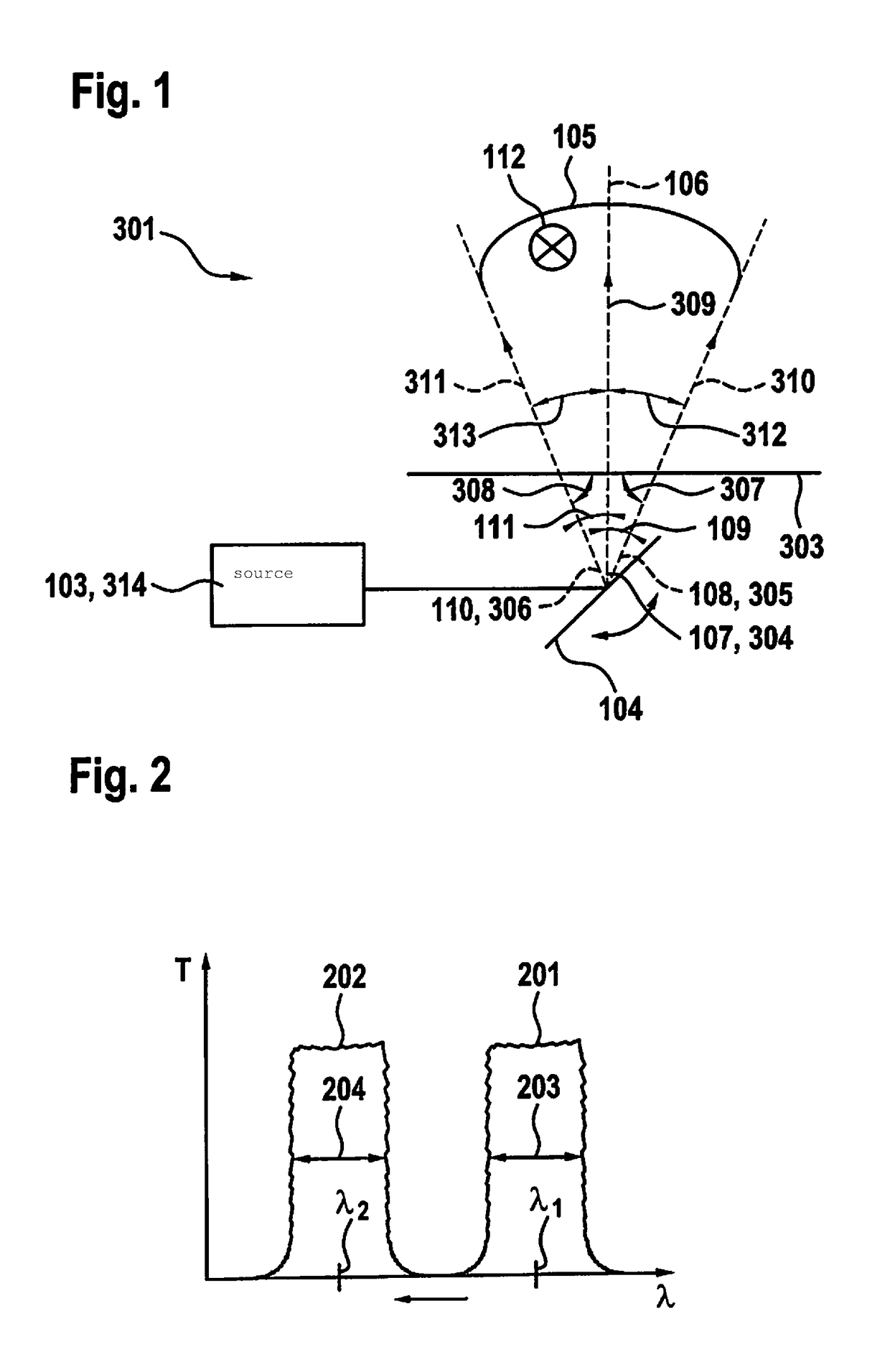
[0043]FIG. 1 shows the structure and beam path of a transmitting unit 301 of a LIDAR sensor according to one embodiment variant of the present invention. Transmitting unit 301 includes a source 103 or 314, a deflection unit 104 and a transmit filter element 303. Line 106 marks the orientation of the optical axis of transmitting unit 301 into the sensing region. The sensing region is depicted two-dimensionally in the example. It spans an angular range 105. The sensing region may also be three-dimensional and be spanned by a solid angle.

[0044]Electromagnetic radiation may be emitted by source 103 or 314. The source may be designed as a laser 103 or 314. The emitted electromagnetic radiation strikes a deflection unit 104 and is deflected by the deflection unit along various directions into the sensing region. The electromagnetic radiation is deflected at various angles into the sensing region. The deflection may take place, for example, along deflection directions 107, 108 and 110. The...


PUM


Abstract

A LIDAR sensor for detecting an object within a sensing region and a method for activating a LIDAR sensor. The LIDAR sensor includes at least one transmitting unit. The transmitting unit includes at least one source for emitting electromagnetic radiation, and at least one deflection unit for deflecting the electromagnetic radiation emitted by the source into the sensing region along a deflection direction. The transmitting unit further includes at least one transmit filter element for filtering the electromagnetic radiation deflected by the deflection unit, which the electromagnetic radiation strikes along a transmit filter input direction. The transmission behavior of the transmit filter element is a function of the transmit filter input direction.

Description

CROSS REFERENCE[0001]The present application claims the benefit under 35 U.S.C. § 119 of German Patent Application No. DE 102016221292.3 filed on Oct. 28, 2016, which is expressly incorporated herein by reference in its entirety.FIELD[0002]The present invention relates to a LIDAR sensor for detecting an object and a method for activating a LIDAR sensor for detecting an object.BACKGROUND INFORMATION[0003]Conventional sensor devices make it possible to detect objects within a sensing region in the surroundings, for example, of a vehicle. These include, for example LIDAR sensors (LIDAR, Light Detection And Ranging). Electromagnetic radiation is emitted from a source. The electromagnetic radiation reflected or scattered on an object in the surroundings is subsequently received by a receiving unit. Not only is the useful signal detected and measured, however, but also noise from the background radiation. Optical bandpass filters (interference filters) are used to block the background rad...

Claims


Application Information

Patent Timeline
IPC IPC(8): G01S7/481
CPCG01S7/4814G01S7/4816G01S7/4817G01S17/02G01S17/42
Inventor HOLLECZEK, ANNEMARIEHEUSSNER, NICOSPIESSBERGER, STEFAN
Owner ROBERT BOSCH GMBH
Why Eureka
Try Eureka