Distance measuring device and distance image synthesizing method

a distance measurement and distance image technology, applied in the direction of distance measurement, instruments, surveying and navigation, etc., can solve the problems of reducing the s/n ratio, reducing the precision in the measurement of the distance, and reducing so as to achieve high precision and increase the sensitivity of the pixel signal before synthesis

Active Publication Date: 2018-05-03
NUVOTON TECH CORP JAPAN
View PDF0 Cites 10 Cited by
  • Summary
  • Abstract
  • Description
  • Claims
  • Application Information

AI Technical Summary

Benefits of technology

[0015]The present disclosure enables synthesis processing according to the signal level of the pixel signal, and can treat with a change in intensity of the reflected light caused by the reflectance of the target object. Furthermore, because all the effective pixel information is used, the sensitivity of the pixel signal before synthesis can also be increased even if the pixel signal h...

Problems solved by technology

Unfortunately, the intensity of the reflected light to be received significantly varies depending on the distance to the target object or its surface reflectance; hence, the measurement of the distance cannot always have high precision across the entire distance image whatever exposure setting is determined.
Conversely, when the exposure amount is decreased, weak light is reflected from an object in a long distance or an object having low surface reflectance becomes weak, reducing the S/N ratio.
Both cases reduce the precision in the measurement of the distance.
Unfortunately, the distance measuring...

Method used


Image

  • Distance measuring device and distance image synthesizing method
  • Distance measuring device and distance image synthesizing method
  • Distance measuring device and distance image synthesizing method

Examples


embodiment 1

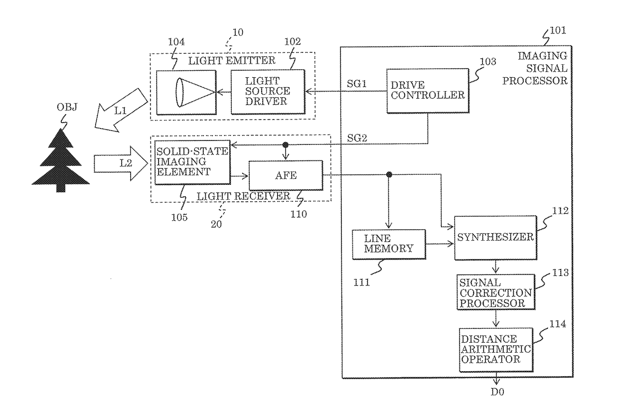
[0041]Although the distance image can be generated by any technique, the following embodiment will be described by way of an example using a Time of Flight (TOF) method of measuring a distance to a target object by irradiating the target object with infrared light or laser light to determine the round-trip time of the light.

[0042]FIG. 1 is a block diagram illustrating a configuration of the distance measuring device according to Embodiment 1. The distance measuring device illustrated in FIG. 1 includes imaging signal processor 101, light emitter 10, and light receiver 20. Imaging signal processor 101 includes drive controller 103, line memory 111, synthesizer 112, signal correction processor 113, and distance arithmetic operator 114. Light emitter 10 includes light source driver 102 and light source 104. Light receiver 20 includes solid-state imaging element 105 and analog front end (AFE) 110.

[0043]Examples of the light emitted from light source 104 include infrared light and laser....

embodiment 2

[0084]In Embodiment 2, another example of the distance measuring device described in Embodiment 1 will be described. In the present embodiment, the condition on measurement of the pixel is switched for every frame to exchange two regions AR1 and AR2 in solid-state imaging element 105 in units of frames.

[0085]FIG. 9 is a diagram illustrating an arrangement pattern of two regions AR1 and AR2 in the present embodiment. The condition on measurement is switched between the current frame and the previous frame to exchange the lines of regions AR1 for those of regions AR2, and vice versa. In such an arrangement pattern of regions AR1 and AR2, the signal to be obtained on the first condition and the signal to be obtained on the second condition can be generated in the spatially same pixel position by using both of the pixels in the current frame and the previous frame. Such a pattern can prevent a reduction in resolution even if the pixels of solid-state imaging element 105 are divided into...


PUM


Abstract

A distance measuring device includes: a light emitter which emits light from a light source to a target object; a light receiver which receives reflected light in a group of pixels two-dimensionally disposed, the reflection light being generated through reflection of the light emitted from the light emitter on the target object; a synthesizer which generates a synthesized signal by synthesizing pixel signals read from pixels exposed at different exposure intervals to generate a synthesized signal; and a distance arithmetic operator which calculates a value of distance to the target object based on the synthesized signal and the difference in time between emission and reception of the light. The synthesizer generates the synthesized signal by the first synthesis processing when a pixel signal of a pixel exposed at a first exposure interval has a signal level higher than a predetermined saturation level, and generates the synthesized signal by second synthesis processing the pixel signal of the pixel exposed at the first exposure interval has a signal level lower than the predetermined saturation level.

Description

CROSS REFERENCE TO RELATED APPLICATIONS[0001]This application is a U.S. continuation application of PCT International Patent Application Number PCT / JP2016 / 003132 filed on Jun. 30, 2016, claiming the benefit of priority of Japanese Patent Application Number 2015-134677 filed on Jul. 3, 2015, the entire contents of which are hereby incorporated by reference.BACKGROUND1. Technical Field[0002]The present disclosure relates to distance image synthesizing methods, and particularly relates to a distance image synthesizing method in a distance measuring device measuring a distance with a light source and a solid-state imaging element using delay of light.2. Description of the Related Art[0003]Devices and methods of generating images including information of a measured distance to a target object (hereinafter, referred to as distance image) have been used in the fields of games and amusements. In recent years, attention has been paid to such devices and methods in applications to and technic...

Claims


Application Information

Patent Timeline
IPC IPC(8): G01S7/486G01S17/08G01C3/08G01S7/4865G01S7/4863G01S17/10G01S17/89
CPCG01S7/4865G01S17/08G01C3/08G01S17/89G01S17/10G01S7/4863
Inventor NISHIKAWA, MAYUMORI, KEIICHI
Owner NUVOTON TECH CORP JAPAN
Why Eureka
Try Eureka