Coplanar high fill factor pixel architecture

a high-fill factor, coplanar technology, applied in the direction of radiation intensity measurement, instruments, x/gamma/cosmic radiation measurement, etc., can solve the problems of pixel fill factor decreasing, pixel fill factor not staying constant, sensor performance degradation, etc., to improve coplanar pixel sensitivity, and higher fill factor

Inactive Publication Date: 2011-03-08
CARESTREAM HEALTH INC
View PDF14 Cites 24 Cited by
  • Summary
  • Abstract
  • Description
  • Claims
  • Application Information

AI Technical Summary

Benefits of technology

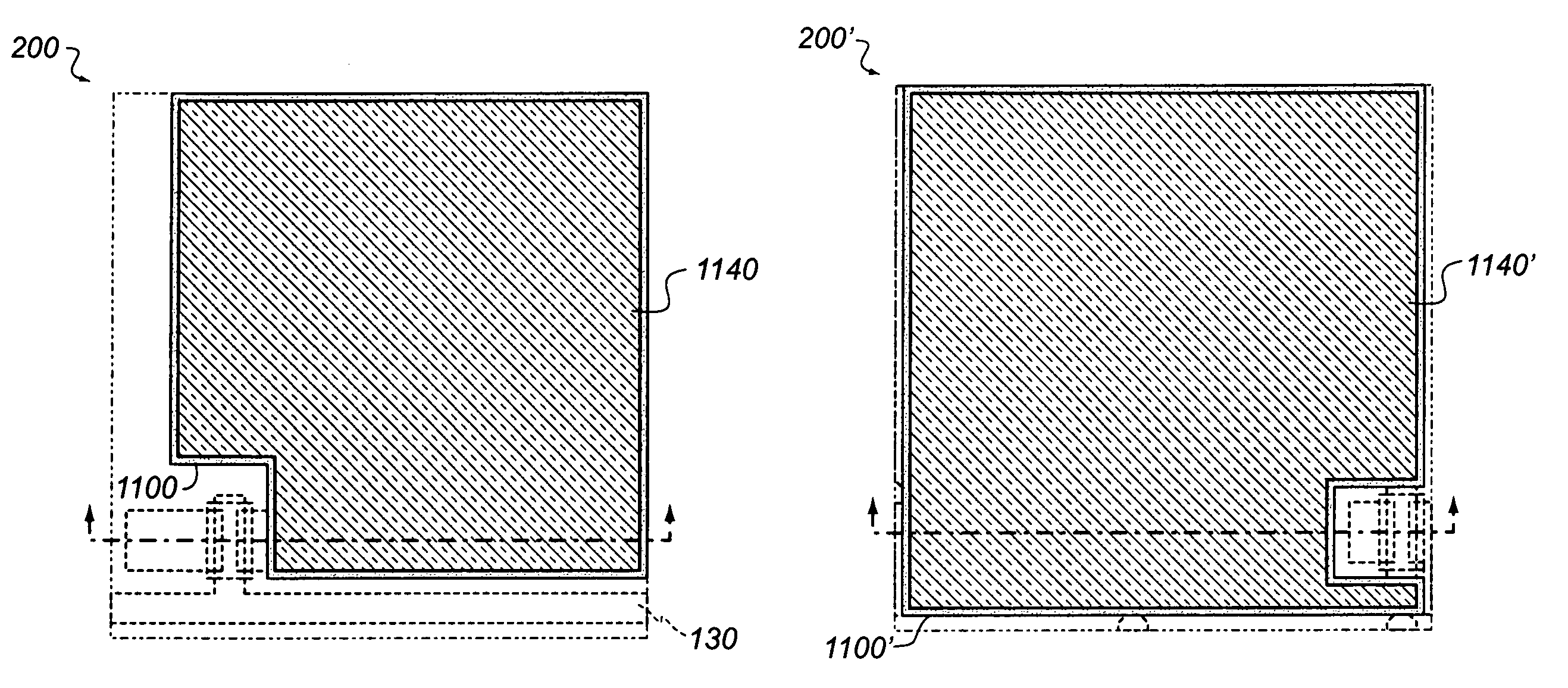
is to improve the coplanar pixel sensitivity by achieving higher fill factor. Another object of the present invention is to improve the coplanar pixel sensitivity for smaller pixel sizes by achieving smaller reduction in pixel fill factor with reduction in pixel size.

Problems solved by technology

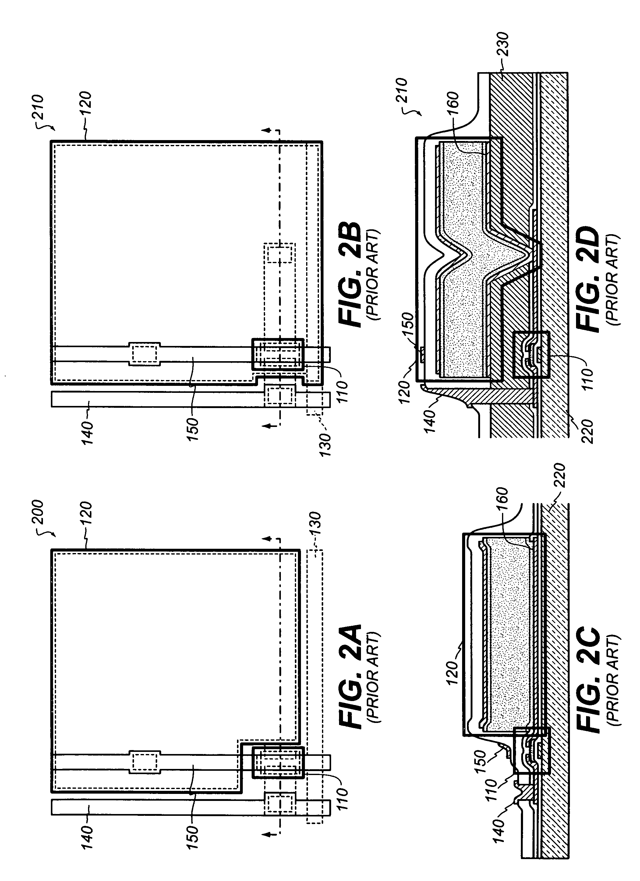
However, issues related with the vertically-integrated pixel architecture 210, for example, added layer stress and degraded sensor performance due to large variation in underlying topology (illustrated in FIG. 2D), can make the coplanar pixel 200 the preferred pixel architecture.
Due to various limitations imposed by the fabrication process of the imaging array, for example, minimum feature size, the pixel fill factor does not stay constant with varying pixel sizes.
The pixel fill factor generally decreases with decreasing pixel pitch and this reduction can be more severe for smaller pixel sizes.

Method used


Image

  • Coplanar high fill factor pixel architecture
  • Coplanar high fill factor pixel architecture
  • Coplanar high fill factor pixel architecture

Examples


Embodiment Construction

Reference will now be made in detail to the present embodiments (exemplary embodiments) of the invention, an example of which is illustrated in the accompanying drawings. Wherever possible, the same reference numbers will be used throughout the drawings to refer to the same or like parts.

For simplicity and illustrative purposes, the principles of the present invention are described by referring mainly to exemplary embodiments thereof. However, one of ordinary skill in the art would readily recognize that the same principles are equally applicable to, and can be implemented in, all types of secure distributed environments and that any such variations do not depart from the true spirit and scope of the present invention. Moreover, in the following detailed description, references are made to the accompanying figures, which illustrate specific embodiments. Electrical, mechanical, logical and structural changes can be made to the embodiments without departing from the spirit and scope o...


PUM


Abstract

A pixel comprising a scan line proximate to a first surface of a substrate and a bias line between the first surface of the substrate and a first terminal of a photosensing element, where a portion of the bias line is substantially parallel to the scan line. The pixel can also comprise a switching element proximate to the first surface of the substrate and aligned with at least a portion of the scan line. The pixel can include the photosensing element proximate to the first surface of the substrate and aligned with at least a portion of the bias line.

Description

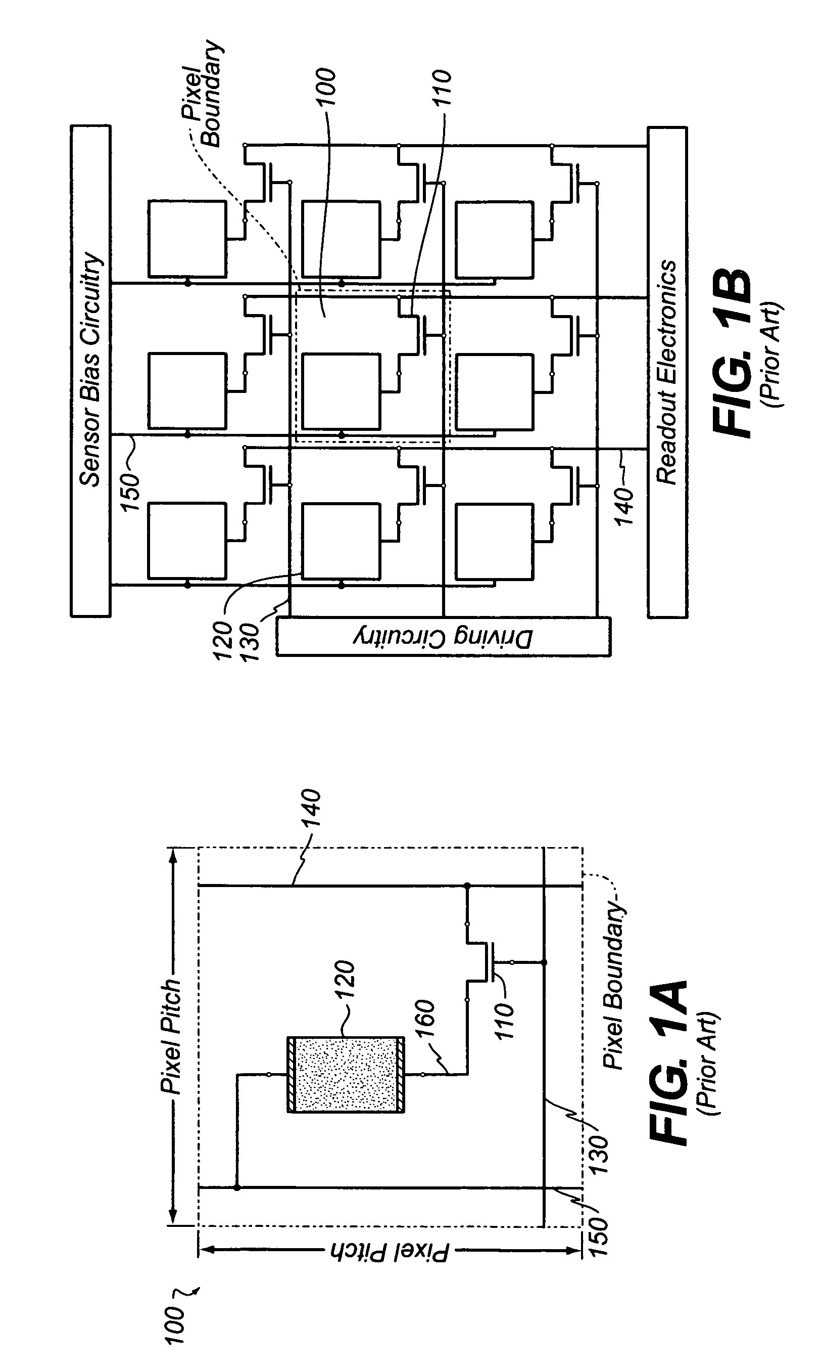
FIELD OF THE INVENTIONThe present invention relates to pixels used in imaging arrays. More specifically, the invention relates to coplanar pixels having relatively high fill factor suitable for use in visible and X-ray image sensing applications, which can include medical diagnostics, non-destructive inspection, etc.BACKGROUND OF THE INVENTIONImaging arrays comprised of multiple sensor pixels 100 are well known in the imaging art. Sensor pixels 100 typically include a switching element 110 such as a thin-film transistor (TFT) and a photoelectric conversion element 120 such as a photodiode. FIG. 1A shows a schematic equivalent pixel circuit for sensor pixels 100. The photoelectric conversion element 120 is sensitive to incident radiation and can generate a number of charge carriers where the number depends on the radiation dosage. In imaging arrays composed of a plurality of pixels, the photogenerated carriers are usually temporarily stored either across the internal capacitance of t...

Claims


Application Information

Patent Timeline
Patent Type & Authority Patents(United States)
IPC IPC(8): G01T1/24
CPCH01L27/14603H01L27/14609H01L27/14612H01L27/14658H01L27/14636H01L27/14659H01L31/022408H01L27/14692
Inventor CHANG, JEFF HSINTREDWELL, TIMOTHY J.HEILER, GREGORY N.
Owner CARESTREAM HEALTH INC
Why Eureka
Try Eureka