Liquid crystal display having light valve

a technology of liquid crystal display and light valve, which is applied in the field of liquid crystal display, can solve problems such as deterioration or distortion of visual data, and achieve the effect of minimizing the aperture ratio reduction

Active Publication Date: 2018-05-03
LG DISPLAY CO LTD
View PDF11 Cites 6 Cited by
  • Summary
  • Abstract
  • Description
  • Claims
  • Application Information

AI Technical Summary

Benefits of technology

[0070]FIG. 6 shows that the thin film transistor T has a small rectangular shape at one corner of the unit pixel area having the rhombus shape. However, the shape of the thin film transistor T is not restricted this shape. For example, the thin film transistor T may have a triangular shape. Otherwise, the thin film transistor T may have a segment shape and be disposed as overlapping with any one side of the rhombus of the unit pixel area UPL of the light valve panel LV. It is preferable that the thin film transistor T of the light valve panel LV has the shape for minimizing the aperture ratio reduction of the video display panel RV. Further, the location of the thin film transistor T of the light valve panel LV may be defined as minimizing the aperture ratio reduction of the video display panel RV.

Problems solved by technology

Any situations are not permitted for causing the deterioration or distortion of the visual data on the instrument panel when conducting the touch operation.

Method used


Image

  • Liquid crystal display having light valve
  • Liquid crystal display having light valve
  • Liquid crystal display having light valve

Examples


first embodiment

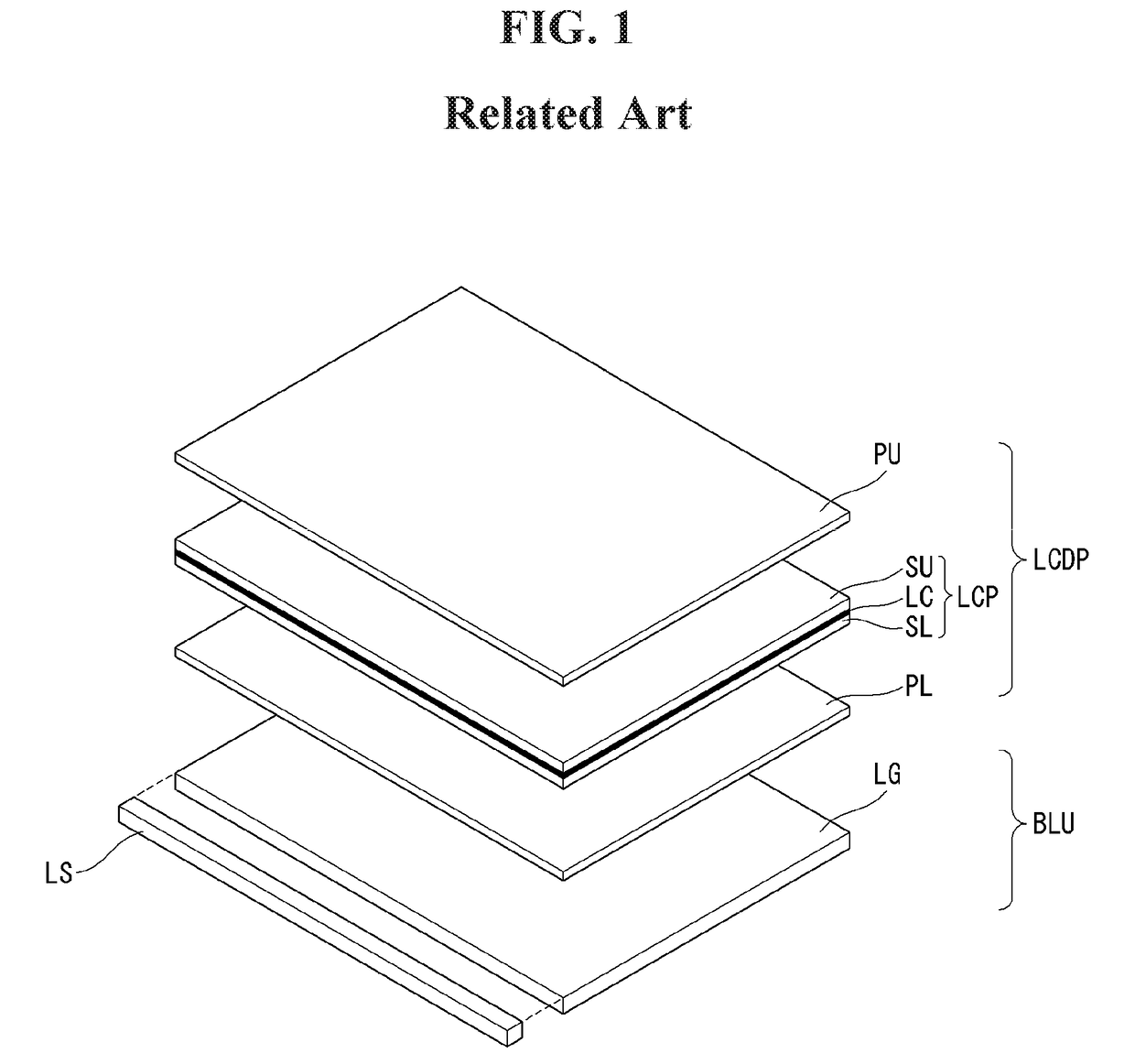
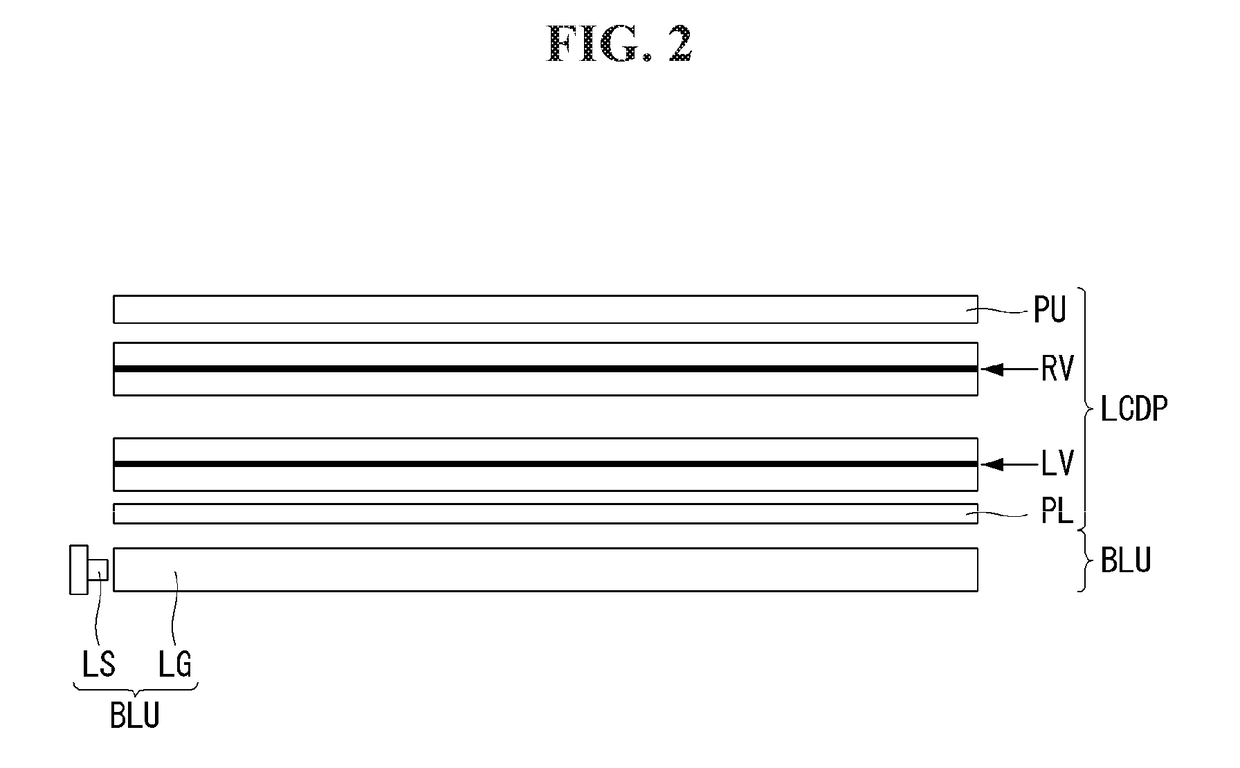
[0031]Referring to FIG. 2, we will explain about the first preferred embodiment of the present disclosure. FIG. 2 is a cross-sectional view illustrating a structure of a liquid crystal display having a light valve according to the present disclosure. A liquid crystal display having a light valve according to the first embodiment of the present disclosure comprises a display panel LCDP and a back light unit BLU.

[0032]The display panel LCDP includes a lower polarization plate PL, a light valve panel LV, a video display panel RV and an upper polarization plate PU. The video display panel RV is disposed on the light valve panel LV.

[0033]For the case that the light valve panel LV and the video display panel RV are made of the liquid crystal display panel, the polarization plates are required. For example, the lower polarization plate PL is disposed under the rear surface of the light valve panel LV. The upper polarization plate PU is disposed on the front surface of the video display pan...

second embodiment

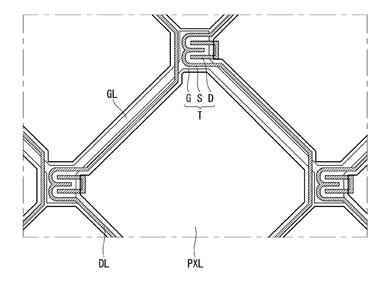
[0052]Hereinafter, referring to FIG. 5, we will explain about the second embodiment of the present disclosure. In the second embodiment, a structure is provided of the liquid crystal display having a light valve in which the light noise pattern such as moiré is not occurred and the aperture ratio is not reduced. FIG. 5 is a plan view illustrating a placement structure of a liquid crystal panel for the light valve and a liquid crystal panel for the video image in a liquid crystal display having a light valve according to the second embodiment of the present disclosure. As the structure of the cross sectional view is same with the first embodiment, we may refer to FIG. 2 also.

[0053]The liquid crystal display according to the second embodiment of the present disclosure comprises a display panel LCDP and a back light unit BLU. The display panel LCDP includes a lower polarization plate PL, a light valve panel LV, a video display panel RV and an upper polarization plate PU. The video disp...


PUM

PropertyMeasurementUnit
areasaaaaaaaaaa
sizeaaaaaaaaaa
areaaaaaaaaaaa

Abstract

The present disclosure relates to a liquid crystal display (or, LCD) including a light valve. The present disclosure provides a liquid crystal display comprising: a back light unit; a light valve panel disposed in front of the back light unit, and including a plurality of first unit pixel areas; and a video display panel disposed in front of the light valve panel, and including a plurality of second unit pixel areas.

Description

CROSS-REFERENCE TO RELATED APPLICATION[0001]This application claims priority to Republic of Korea Patent Application No. 10-2016-0142970 filed on Oct. 31, 2016, which is incorporated by reference herein in its entirety.BACKGROUNDTechnical Field[0002]The present disclosure relates to a liquid crystal display (or, LCD) including a light valve. Especially, the present disclosure relates to a liquid crystal display having a first liquid crystal display for the light valve and a second liquid crystal display for the video display in which the black and white contrast is enhanced.Description of the Related Art[0003]Thanks to the characteristics such as the light weight, the thin thickness and the low power consumption, the liquid crystal displays are widely used for various applications. The liquid crystal displays are used for the portable computer, the office automation appliances, the audio / video devices, the commercial displays and so. The most type of the liquid crystal display, the ...

Claims


Application Information

Patent Timeline
Patent Type & Authority Applications(United States)
IPC IPC(8): G02F1/1362G02F1/1368
CPCG02F1/136286G02F1/1368G02F2001/133601G02F1/133528G02F2001/136222G02F2201/123G02B6/0055G02F1/133509G02F1/133514G02F1/13471G02F1/133524G02F1/133615G02F1/13338G02F1/1343G02F1/133601G02F1/136222
Inventor KIM, WONDOOPARK, KIBOKLEE, JOONDONGKIM, KAKYUNG
Owner LG DISPLAY CO LTD
Why Eureka
Try Eureka