
Multiphase power supply and phase control

a multi-phase power supply and phase control technology, applied in the direction of electric variable regulation, process and machine control, instruments, etc., can solve the problems of reducing the efficiency of multi-phase semi-resonant converters, the interval of half-cycle sinusoidal shapes,

Inactive Publication Date: 2018-05-03
INFINEON TECH AUSTRIA AG
View PDF3 Cites 4 Cited by
  • Summary
  • Abstract
  • Description
  • Claims
  • Application Information

AI Technical Summary

Benefits of technology

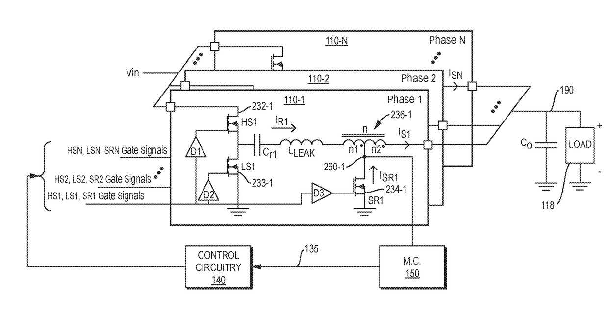
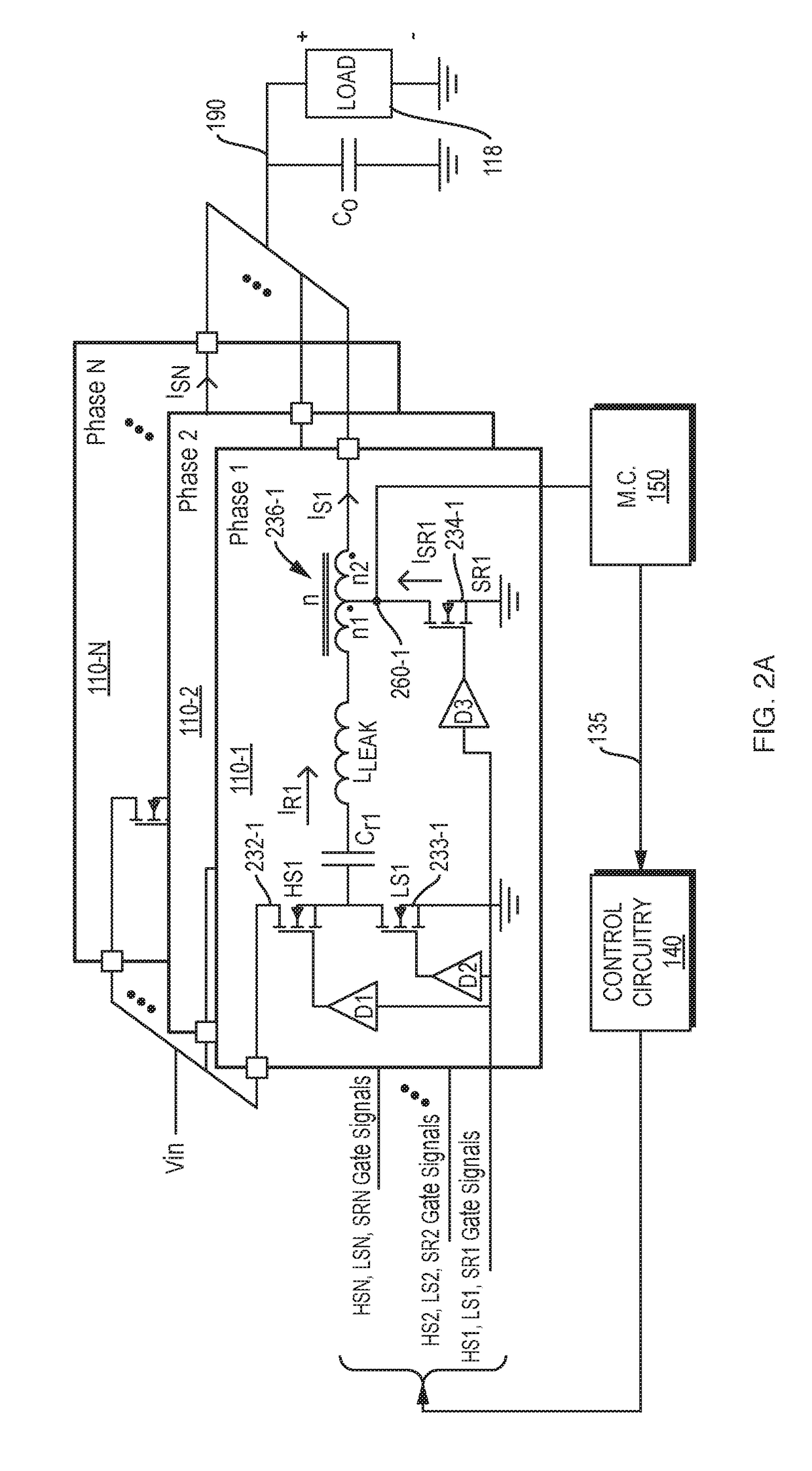
The present disclosure provides a computer program product that controls phases in a power supply to achieve synchronization and higher power conversion efficiency. By controlling the timing of activating / deactivating control switch circuitry in each phase, the program reduces ripple voltage on the output voltage of the multi-phase power supply circuit. Additionally, the program monitors the current in the inductor device and adjusts the timing of activating the control switch in the second phase accordingly. This allows for zero current switching of the different resonant frequency phases and improves the overall power conversion efficiency.

Problems solved by technology

This disclosure includes the observation that a problem with conventional multi-phase semi-resonant converters is that the time interval of the half-cycle sinusoidal-shaped current (linked to the resonant frequency of the phases) will often vary from one phase to another due to variations in the inductance and capacitance of corresponding components associated with each of the phases.
The efficiency of the multi-phase semi-resonant converter is reduced due to the inability to achieve ZCS for the SR switch in every phase of such a voltage converter.

Method used


Image

  • Multiphase power supply and phase control
  • Multiphase power supply and phase control
  • Multiphase power supply and phase control

Examples


Embodiment Construction

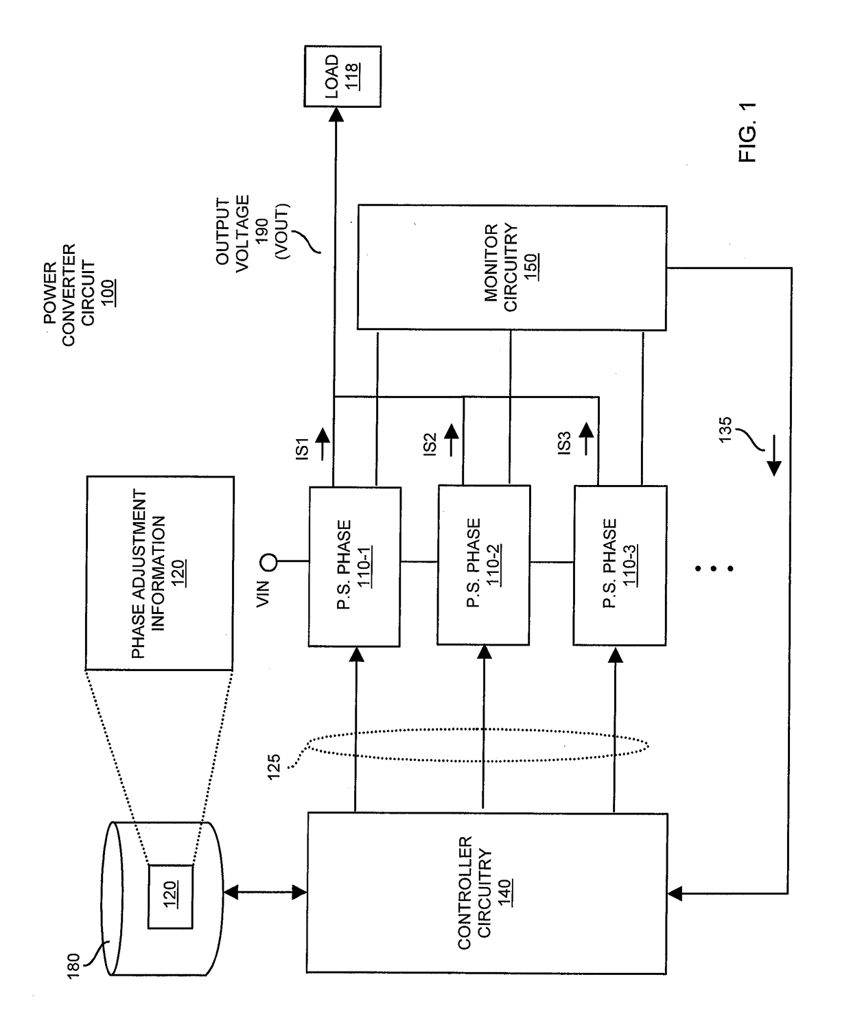
[0039]Now, more specifically, FIG. 1 is an example diagram of a power converter circuit and respective circuitry according to embodiments herein.

[0040]As shown, the power converter circuit 100 includes multiple phases 110 (such as phase 110-1, phase 110-2, phase 110-3, etc.). Additionally, power converter circuit 100 includes controller circuitry 140 and monitor circuitry 150.

[0041]Each of the multiple phases 110 receives input voltage (Vin) such as a DC (Direct Current) voltage. The phases 110 collectively produce output voltage 190 (Vout such as a DC voltage). Thus, the power converter circuit 100 can be a DC to DC power converter.

[0042]In one embodiment, the controller circuitry 140 is operable to produce and then use phase adjustment information 120 to generate control signals 125 that, in turn, control respective phases 110 and delivery of current IS1, IS2, IS3, etc., to the load 118.

[0043]More specifically, during operation, the monitor circuitry 150 monitors a respective node...


PUM


Abstract

A multi-phase power supply circuit includes at least a first phase and a second phase (such as semi-resonant DC-DC power converter circuits), each of which output current to power a load. The first phase includes a first inductor device through which first current is delivered to the load. The second phase includes a second inductor device through which second current is delivered to the load. A current monitor circuit of the multi-phase power supply circuit is operable to monitor current through the second inductor device. Control circuitry of the multi-phase power supply circuit is operable to adjust timing of activating a control switch in the second phase to an ON state based on the monitored current. Timing of the phases is adjusted to achieve a common switching and zero current switching amongst the phases.

Description

BACKGROUND[0001]One class of conventional semi-resonant power converter circuits includes high-side (such as control switch circuitry) and low-side switches (synchronous switch circuitry) that transfer power from an input source to a tapped inductor that supplies output power to a load. In such conventional semi-resonant power converter circuits, a tapped inductor is also connected to a second low-side switch, namely, a synchronous rectification (SR) switch.[0002]In order to meet the power requirements for a load of a semi-resonant converter (e.g., provide a near constant output voltage for the load), many conventional semi-resonant DC-DC converters employ a variable switching frequency in which a respective switching period of each phase varies from cycle to cycle. During a portion of each switching period, the SR switch is enabled such that current flows through it. For the semi-resonant converter described above, the current during this portion of a switching period will be shape...

Claims


Application Information

Patent Timeline
Patent Type & Authority Applications(United States)
IPC IPC(8): H02M1/084H02M3/156H02M1/14H02M1/08
CPCH02M1/084H02M3/156H02M3/158H02M1/083H02M1/14H02M3/1584H02M1/0058H02M3/1586Y02B70/10
Inventor SREENIVAS, VENKATBABAZADEH, AMIR
Owner INFINEON TECH AUSTRIA AG
Learn More