Axial swage tool

Active Publication Date: 2018-05-10
AEROFIT LLC
View PDF10 Cites 0 Cited by
  • Summary
  • Abstract
  • Description
  • Claims
  • Application Information

AI Technical Summary

Benefits of technology

[0004]Swage tools with complex designs can include many moving components, which are subject to wear. In such tools, each component contributes to tolerance buildup, and each

Problems solved by technology

Swage tools with complex designs can include many moving components, which are subject to wear.
In such tools, each component contributes to tolerance buildup, and each area of contact between moving parts is subject to wear.
Additional wear results in increased costs, replacement of parts, and decreased performance over the life of the tool.
Ad

Method used


Image

  • Axial swage tool
  • Axial swage tool
  • Axial swage tool

Examples


Embodiment Construction

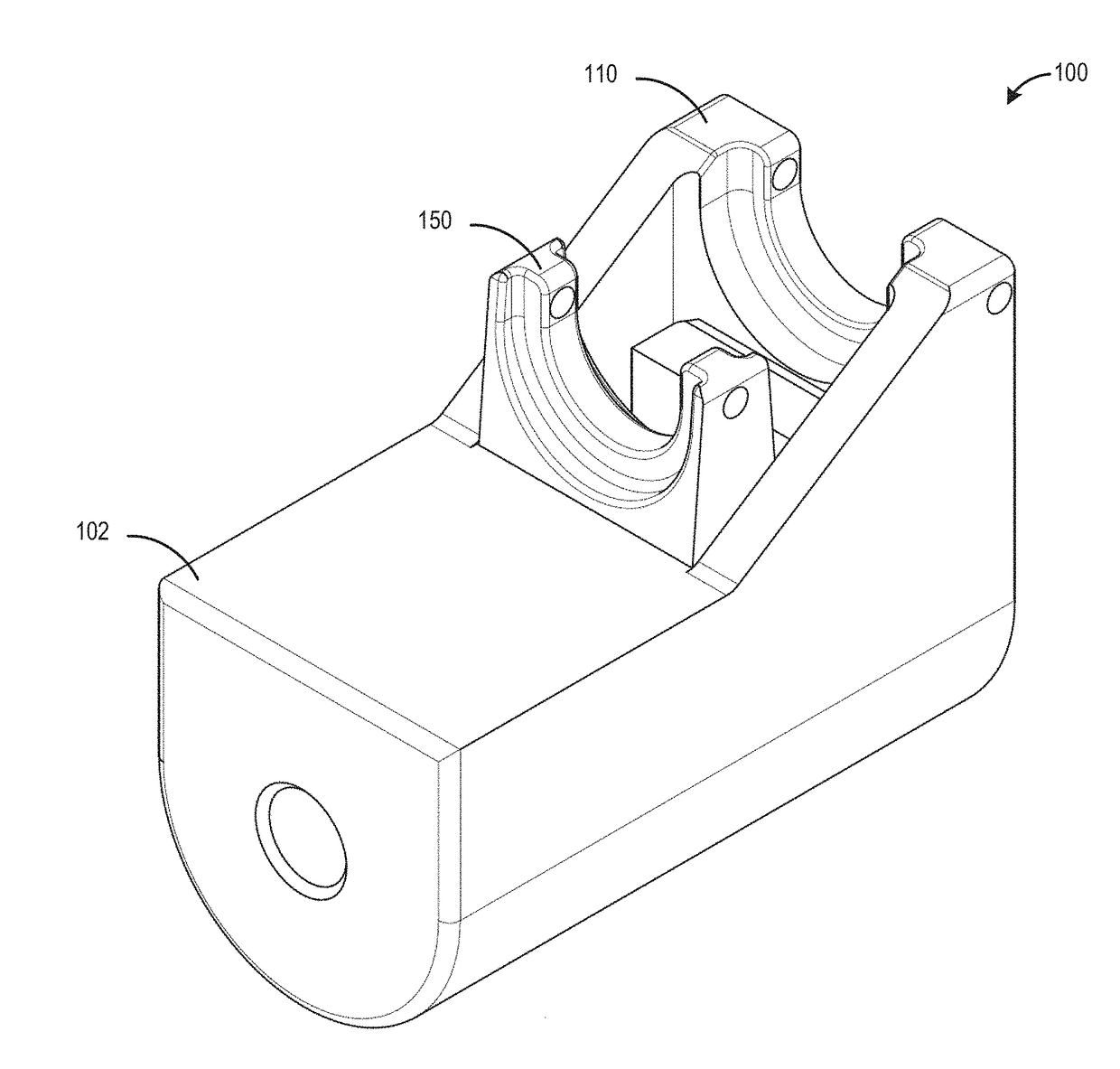
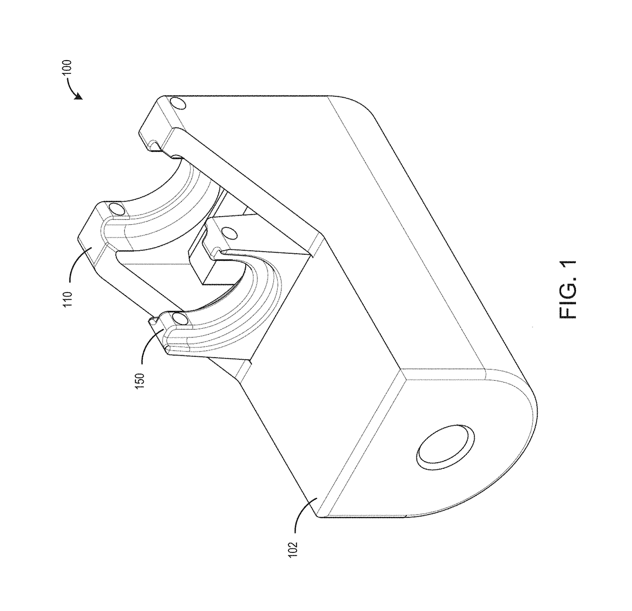
[0026]Embodiments of the present disclosure provide an axial swage tool configured to axially swage a fitting to a tube, a cable, or other such item of manufacture. The swage tool can be configured to utilize swaging engagement members for grasping and driving a swaging ring over a fitting. The swaging ring thereby radially compresses the fitting around the tube or other item.

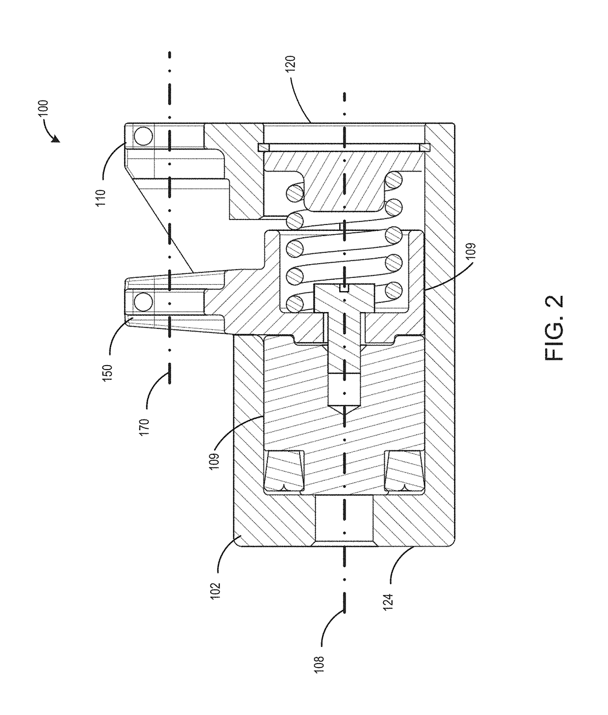
[0027]With reference to FIGS. 1-4, an embodiment of an axial swage tool 100 is illustrated. The axial swage tool 100 includes a housing 102 having an inner surface 104 that forms a chamber106. The chamber 106 can have a longitudinal axis 108, also referred to as a chamber axis. The housing 102 includes a fixed jaw unit 110, also referred to as a swaging engagement member. In some embodiments, the jaw unit 110 can be formed into the housing 102. The swage tool 100 also includes a movable jaw 150 having a first portion 151, also referred to as the chamber portion, and a second portion 160, also referred to as the...


PUM


Abstract

Embodiments of the present disclosure provide an axial swage tool configured to axially swage a fitting to a tube, a cable, or other such item of manufacture. The swage tool can be configured to utilize swaging engagement members for grasping and driving a swaging ring over a fitting. The swaging ring thereby radially compresses the fitting around the tube or other item.

Description

BACKGROUNDField[0001]The present disclosure relates to tools for use in swaging and, more particularly, to a swaging tool for swaging axially swaged fittings.Description of the Related Art[0002]Swaged fittings have been used for many years to connect tubes and pipes in various types of systems, including fluid systems used in the aircraft, marine, petroleum and chemical industries, as well as power transmission systems and the like. In a typical fluid system, the ends of two tubes are inserted into opposing ends of a fitting, each of which is usually in the form of a cylindrical sleeve or other type of fitting body. The fitting is then swaged with a swaging tool to produce a fluid-tight connection placing the tubes in fluid communication. This swaging operation is normally carried out by applying a radial force that radially compresses the fitting and tubing inwardly. This radial force may be applied directly by the swaging tool or indirectly by a specially shaped ring that is moved...

Claims


Application Information

Patent Timeline
IPC IPC(8): B25B27/10
CPCB25B27/10
Inventor GALLEGOS, ROBERTSURESH, SRINIVAS B.
Owner AEROFIT LLC
Why Eureka
Try Eureka