
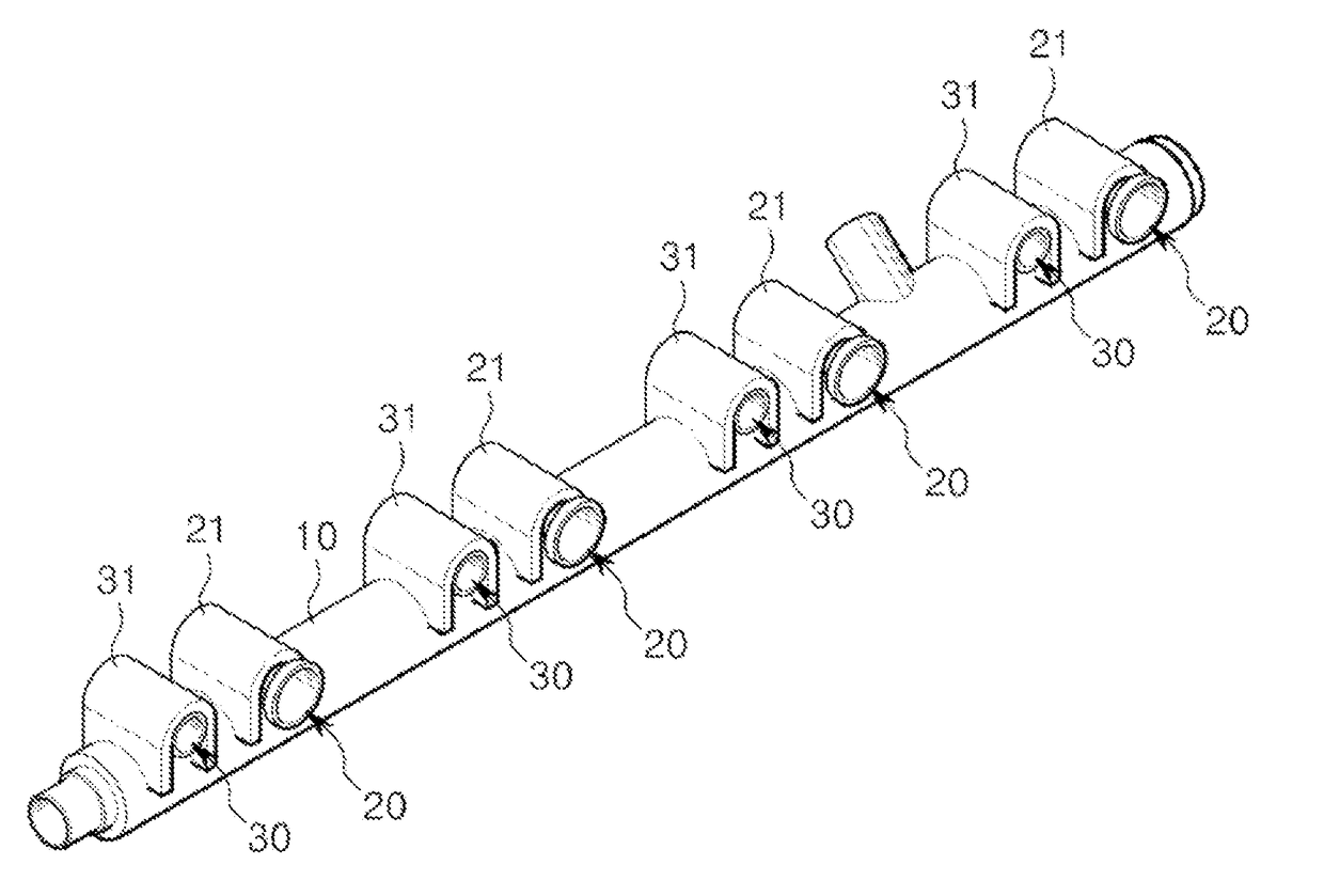
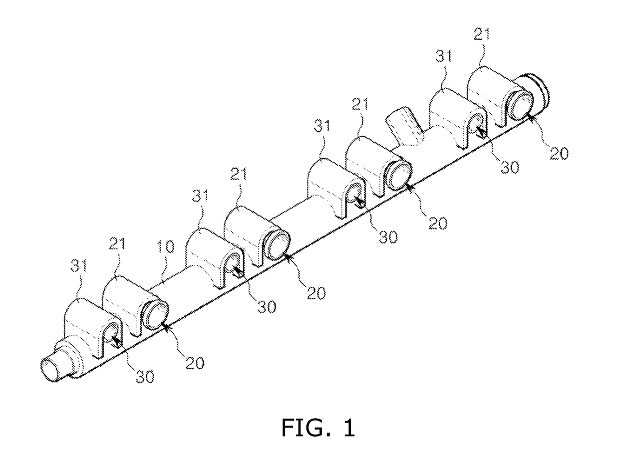
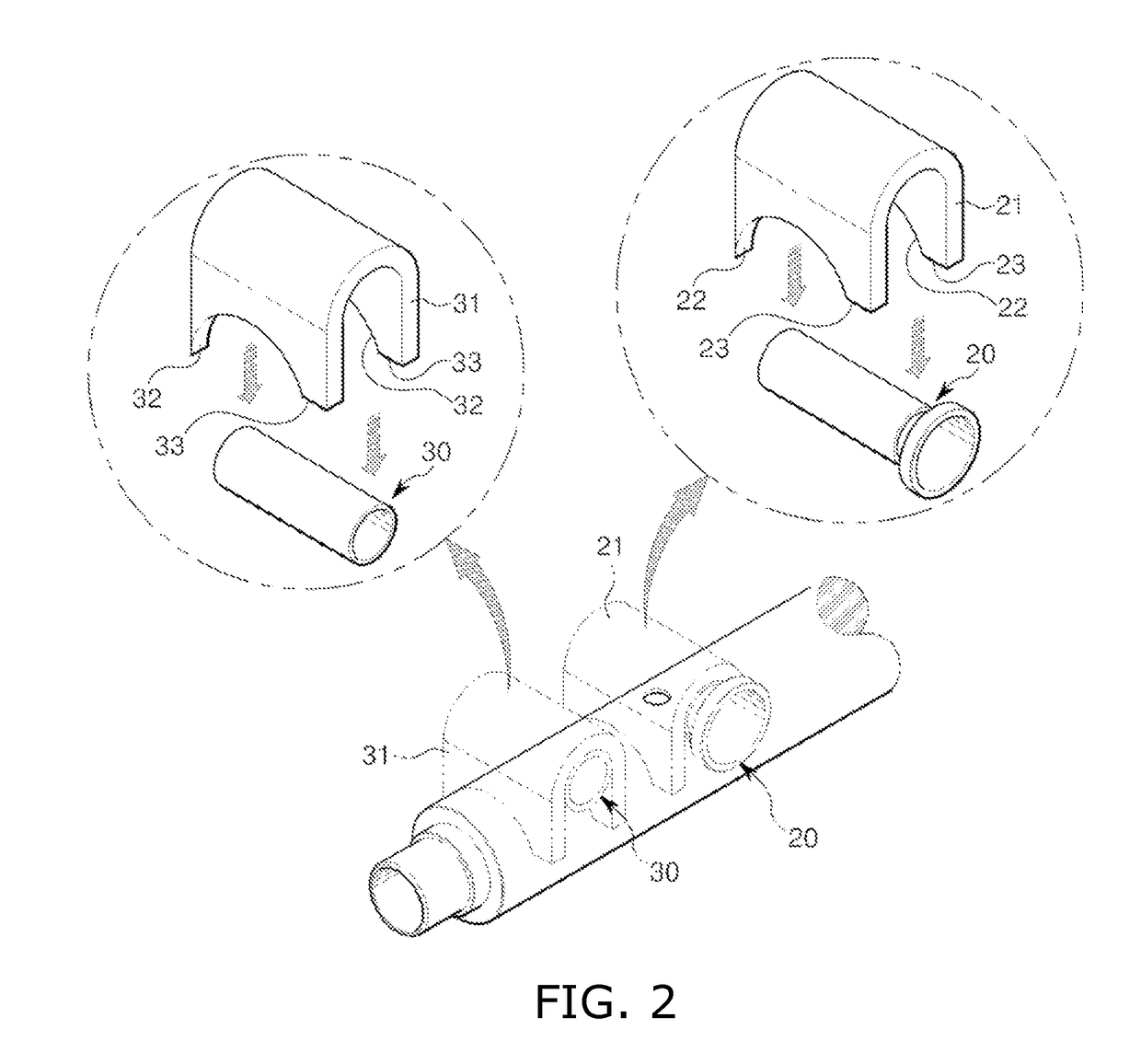
Structure of gdi fuel delivery pipe

a technology of gdi fuel and structure, which is applied in the direction of stress reducing fuel injection, fuel injection apparatus, charge feed system, etc., can solve the problems of fuel rail displacement, cracks in the welded portions, and fatigue stress on the individual parts of the fuel rail, so as to reduce the weight of injector cups and mount holders, the effect of reducing the cost of products and improving repeatability

Active Publication Date: 2018-05-10
DONGBO IND
View PDF5 Cites 4 Cited by
  • Summary
  • Abstract
  • Description
  • Claims
  • Application Information

AI Technical Summary

Benefits of technology

The present invention provides a gasoline direct injection (GDI) fuel delivery pipe that has improved durability against variations in internal pressure and reduces the weight and cost of injector cups and mount holders. The main technical effects of this invention are increased welded areas and locations, providing a shock-absorbing effect against the injection noise of injectors, and reducing weights and costs of products.

Problems solved by technology

Meanwhile, in the above-described conventional GDI-type fuel rail in which the mount structures and the injector cups are independently constructed and the individual structures are attached to the main pipe by using a brazing method, the fuel rail is subjected to displacement due to pressure, heat, or vibration generated in an engine, with the result that fatigue stress is imposed on the individual parts of the fuel rail.
In particular, stress is concentrated on welded (brazed) portions of the mount structures and the injector cups fastened to the engine heads, and thus a problem occurs in that cracks occur in the welded portions.

Method used


Image

  • Structure of gdi fuel delivery pipe
  • Structure of gdi fuel delivery pipe
  • Structure of gdi fuel delivery pipe

Examples


Embodiment Construction

[0016]A preferred embodiment of the present invention will be described in detail below with reference to the accompanying drawings. Prior to the following description, it is noted that the terms or words used in the present specification and the claims should not be interpreted as being limited to common or dictionary meanings but should be interpreted as having meanings and concepts corresponding to the technical spirit of the invention based on the principle in which an inventor may appropriately define the concepts of terms in order to describe his or her invention in the best way.

[0017]Accordingly, the embodiment described in the present specification and the configurations shown in the drawings merely correspond to embodiments of the present invention and do not cover all the technical spirit of the present invention, and thus it should be appreciated that there may be various equivalents that may replace the embodiment and the configurations at the time at which the present a...


PUM


Abstract

Disclosed herein is the structure of a GDI fuel delivery pipe. The structure of a GDI fuel delivery pipe includes: a main pipe configured to flow fuel through a hollow formed therein; a plurality of injector cups formed in cylindrical shapes having open lower ends, and configured to be coupled and fastened to the main pipe, to flow fuel therethrough, and to be coupled to respective injectors; a plurality of mount M holders configured to form tubular parts each having a bolt hole in a lengthwise direction, and to be coupled and fastened to the main pipe; and fastening members configured to fasten the plurality of injector cups or mount holders to the main pipe by being coupled to the outer circumferential surface of the main pipe at both left and right ends thereof while surrounding the outer circumferences of the plurality of injector cups or mount holders.

Description

BACKGROUND1. Technical Field[0001]The present invention relates to the structure of a GDI fuel delivery pipe, and more specifically to the structure of a gasoline direct injection (GDI) fuel delivery pipe in which each of injector cups and mount holders coupled to a main pipe is constructed in at least two separate structures, and welded areas and locations are increased compared to conventional areas and locations, thereby improving repetition durability (pulsation fatigue durability) against variations in pressure.2. Description of the Related Art[0002]Recently, in order to meet regulation on exhaust gas which has been tightened all over the world, various technologies have been developed and actually applied.[0003]Of these technologies, a gasoline direct injection (GDI)-type engine increases combustion efficiency by directly injecting high-pressure fuel into a combustion chamber, thereby reducing exhaust gas and also improving fuel efficiency and output. Accordingly, the developm...

Claims


Application Information

Patent Timeline
IPC IPC(8): F02M55/00F02M55/02
CPCF02M55/005F02M55/025F02M2200/315F02M2200/857F02M61/14F02M2200/03F02M2200/09F02M2200/856F02M69/465F02M2200/8084F02M55/004F02M55/02F02M55/04
Inventor PARK, SEE WOOLEE, SU HWIYU, SU JINLEE, KEUN SIK
Owner DONGBO IND
Learn More