Modification Example
[0108]FIG. 11 is a functional block diagram for illustrating a schematic configuration of a first gas meter 300 according to a modification example of the present invention. As illustrated in FIG. 11, the first gas meter 300 differs from the above-mentioned first gas meter 110 in that a temperature sensor 302 is provided. The remaining configuration is the same as that of the first gas meter 110.
[0109]The temperature sensor 302 measures the temperature of the supplied gas. Then, the heating value derivation unit 164 derives the unit heating value based on the sound velocity derived by the sound velocity derivation unit 160 and on the temperature measured by the temperature sensor 302. With this, the heating value derivation unit 164 can derive the unit heating value of the gas with higher accuracy than that of the first gas meter 110.
[0110]As described above, the first gas meter 300 can derive or measure the temperature and the sound velocity of the gas to derive the unit heating value of the gas based on the temperature and the sound velocity of the gas. With this, the derivation accuracy of the unit heating value of the gas can be improved.
[0111]The preferred embodiment of the present invention has been described above with reference to the attached drawings, but, needless to say, the present invention is not limited to the embodiment. It is apparent that those skilled in the art may arrive at various alternations and modifications within the scope of claims, and those examples are construed as naturally falling within the technical scope of the present invention.
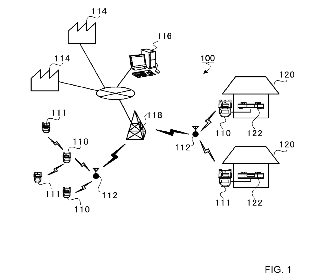
[0112]In the above-mentioned embodiment, the first gas meter 110 includes the heating value derivation unit 164 and the passage heating value derivation unit 166, but the center device 116 may include those units. In this case, the first gas meter 110 may transmit the information of the sound velocity derived by the sound velocity derivation unit 160 to the center device 116.
[0113]Further, in the above-mentioned embodiment, the first gas meter 110 includes the communication circuit 154, but the first gas meter 110 may not include the communication circuit 154. In this case, the unit heating value, the passage heating value, or the flow rate of the gas that has passed through the first gas meter 110 is read by a meter reader for each month, for example. The read unit heating value, passage heating value, or flow rate of the gas may be stored in the center device 116.
[0114]Further, in the above-mentioned embodiment, the second gas meter 111 includes the communication circuit 184, but the second gas meter 111 may not include the communication circuit 184. In this case, the flow rate of the gas that has passed through the second gas meter 111 is read by a meter reader for each month, for example. The read flow rate of the gas is stored in the center device 116. Then, the center device 116 may derive the passage heating value based on the product of the monthly average value of the unit heating value of the first gas meter 110 that is arranged closest to the second gas meter 111 and the read flow rate of the gas.
[0115]Further, in the above-mentioned embodiment, the second gas meter 111 includes the communication circuit 184, but the second gas meter 111 may not include the communication circuit 184. In this case, the flow rate of the gas that has passed through the second gas meter 111 is read by a meter reader for each month, for example. The read flow rate of the gas is stored in the center device 116. Then, the center device 116 may estimate the monthly average unit heating value of the second gas meter 111 based on the monthly average unit heating value of the first gas meter 110 that is arranged closest to the second gas meter 111, and derive the passage heating value based on the product of the estimated monthly average unit heating value and the read flow rate of the gas.
[0116]Further, for example, the unit heating value of the second gas meter 111 may be estimated based on the unit heating value of the first gas meter 110 that is arranged closest among the first gas meters 110 through which a gas is passing during a time period that is the same as the time at which the gas passes through the second gas meter 111. That is, when the first gas meter 110 is not used, even the first gas meter 110 that is arranged closest to the second gas meter 111 may be excluded, and the closest first gas meter 110 may be identified from the first gas meters 110 used during the above-mentioned time period, to thereby estimate the unit heating value of the second gas meter 111 based on the unit heating value of the identified first gas meter 110.
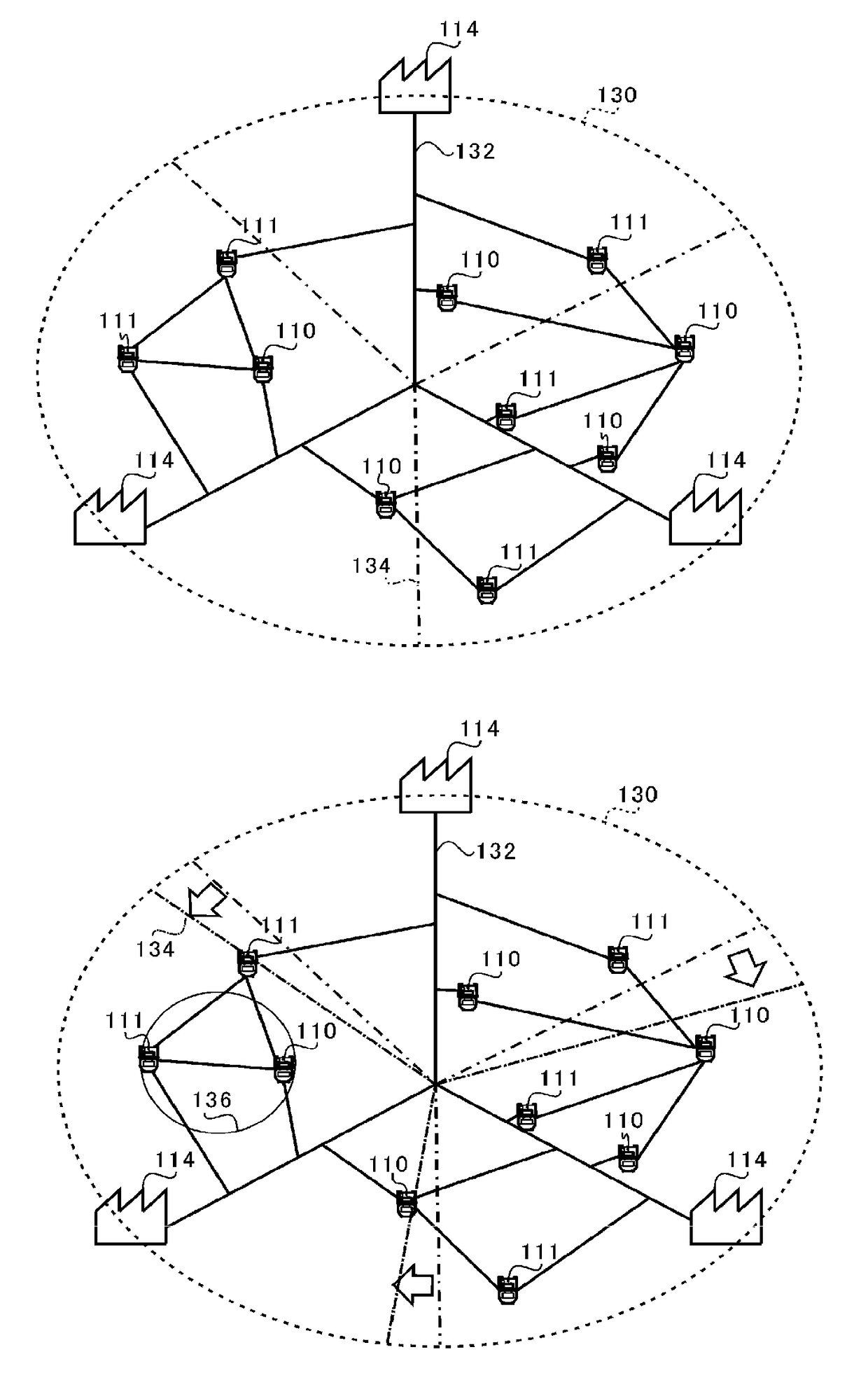
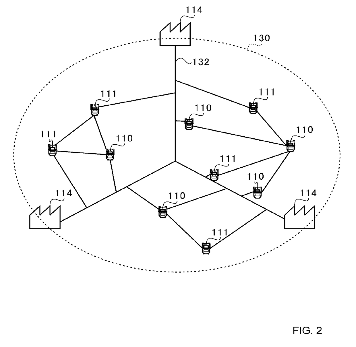
[0117]Further, in the above-mentioned embodiment, the unit heating value of the second gas meter 111 is estimated based on the unit heating value of the first gas meter 110 that is arranged closest, but the unit heating value of the second gas meter 111 may be estimated based on the unit heating value of the first gas meter 110 that falls within a predetermined range 136 (FIG. 10(b)) on the gas supply pipes 132 with respect to the second gas meter 111.
[0118]Further, the first gas meter 300 may derive the heating value in the standard state based on the sound velocity derived by the sound velocity derivation unit 160 and on the temperature measured by the temperature sensor 302 to transmit the derived heating value to the center device 116, and the second gas meter 111 may include a temperature sensor to transmit the temperature measured by the temperature sensor in addition to the passage volume to the center device 116. The center device 116 may derive the unit heating value of the second gas meter 111 based on the heating value in the standard state derived by the first gas meter 300 and on the temperature and the passage volume that are measured or derived by the second gas meter 111.
[0119]Further, each of the first gas meter 110 and the second gas meter 111 may include a pressure sensor configured to measure a pressure of the supplied gas. In this case, the first gas meter 110 may correct the unit heating value based on the pressure measured by the pressure sensor (Expression (8)), and the second gas meter 111 may correct a volumetric flow rate based on the pressure measured by the pressure sensor. Further, the first gas meter 110 may include a pressure sensor configured to measure a pressure of the supplied gas, and the volumetric flow rate of the second gas meter 111 may be corrected based on the pressure measured by the first gas meter 110 close to the second gas meter 111.
[0120]Further, the gas production plant 114 may include gas chromatograph and desirably a sound velocity derivation unit as well. The gas production plant 114 may analyze the component of the produced gas by gas chromatograph to transmit results to the center device 116 as gas characteristics, and may transmit the sound velocity of the gas derived by the sound velocity derivation unit to the center device 116. Then, the center device 116 may identify the producer of the gas supplied to the first gas meter 110, that is, among the plurality of gas production plants 114, the gas production plant 114 producing the supplied gas based on the sound velocity itself or the time-series change of the sound velocity of the gas, which is received from the first gas meter 110, and on the gas characteristic and the sound velocity that are received from the gas production plant 114.
INDUSTRIAL APPLICABILITY
[0121]The present invention can be applied to a gas meter system and a heating value estimation method for deriving a unit heating value.
REFERENCE SIGNS LIST
[0122] 100 gas meter system [0123] 110 first gas meter [0124] 111 second gas meter [0125] 114 gas production plant [0126] 116 center device [0127] 150 ultrasonic flow meter [0128] 160 sound velocity derivation unit [0129] 162 flow rate derivation unit [0130] 164 heating value derivation unit [0131] 166 passage heating value derivation unit (heating value derivation unit) [0132] 212 unit heating value estimation unit [0133] 214 passage heating value derivation unit