
Compact non-mechanical zoom lens

Active Publication Date: 2018-05-10
KENT STATE UNIV
View PDF2 Cites 20 Cited by
  • Summary
  • Abstract
  • Description
  • Claims
  • Application Information

AI Technical Summary

Benefits of technology

The patent describes an optical magnification system that uses a first composite lens and a second composite lens to output light into each other. The first lens has a different focal length for left-handed and right-handed circularly polarized light, while the second lens has a different focal length for left-handed and right-handed circularly polarized light. The system also includes an electro-optic polarization element or sub-system that can switch the circularly polarized light between left-handedness and right-handedness. The system can provide different magnifications for left-hand and right-hand circularly polarized light. The technical effects of the system include improved optical performance and greater flexibility in light manipulation.

Problems solved by technology

However, providing a sufficiently large field of view may limit the spatial resolution.
However, mechanical zoom lens systems are typically bulky, and the zoom speed is limited by the mechanical response time of the zoom system.
This can be problematic for systems that need to be made small, such as a user interface camera designed to fit into the bezel of a portable computer or mobile device, or in systems or devices needing high speed zoom adjustment.

Method used


Image

  • Compact non-mechanical zoom lens
  • Compact non-mechanical zoom lens
  • Compact non-mechanical zoom lens

Examples


Embodiment Construction

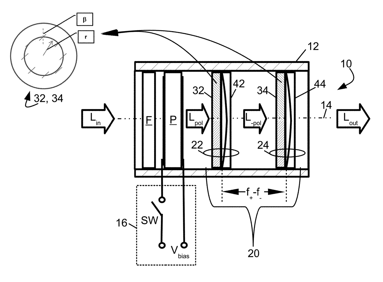
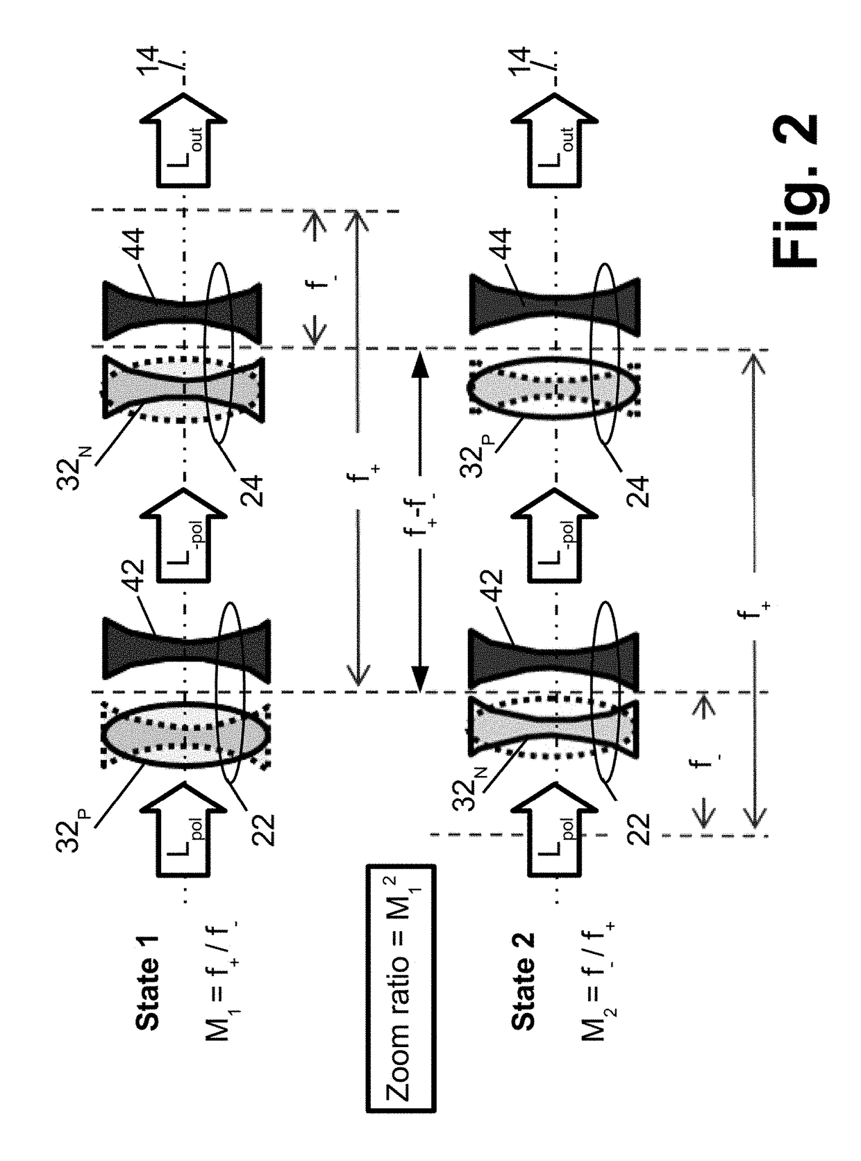
[0018]Disclosed herein are non-mechanical optical zoom systems that leverage certain characteristics of Pancharatnam phase lenses to achieve electrical switching of the optical zoom system between two (or more) zoom settings, e.g. between two different magnifications. Pancharatnam lenses provide focusing of circularly polarized light. The illustrative optical zoom systems leverage a particular property of Pancharatnam phase lenses, namely that the focal length of a Pancharatnam lens switches sign (i.e. switches between a positive focal length and a negative focal length of the same magnitude) when the sign of the circularly polarized light is switched between left-hand circular polarization and right-hand polarization (or, using a different nomenclature, between counter-clockwise circular polarization and clockwise circular polarization). This transformation from a positive lens to a negative lens based on the handedness of the circularly polarized input light, which is a property o...


PUM


Abstract

An optical magnification system comprises two Pancharatnam lenses, and provides a first magnification for left-hand circularly polarized light and a second magnification different from the first magnification for right-hand circularly polarized light. An optical magnification system comprises two lenses, each having different focal lengths for left-handed and right-handed circularly polarized light, respectively, and configured to provide a first magnification for left-handed circularly polarized light and a second magnification different from the first magnification for right-handed circularly polarized light.

Description

[0001]This application is a national stage entry of PCT / US2016 / 024218 filed Mar. 25, 2016 and titled “COMPACT NON-MECHANICAL ZOOM LENS” which claims the benefit of U.S. Provisional Application No. 62 / 138,678 filed Mar. 26, 2015 and titled “COMPACT NON-MECHANICAL ZOOM LENS”. U.S. Provisional Application No. 62 / 138,678 filed Mar. 26, 2015 and titled “COMPACT NON-MECHANICAL ZOOM LENS” is incorporated herein by reference in its entirety.BACKGROUND[0002]The following relates to the optical device arts, optical lens arts, zoom lens arts, and related arts.[0003]Adjustable zoom lenses find diverse applications, such as in machine vision inspection systems, computer vision systems used as input devices by computers, gaming consoles, mobile devices (cell phones, tablet computers, laptop computers), and other interactive electronic devices, and so forth. In a typical system, a monochromatic imaging device including a lens and a digital imaging array (e.g. CCD array, CMOS imaging array, or so f...

Claims


Application Information

Patent Timeline
IPC IPC(8): G02B13/00G02B5/30G02B27/28
CPCG02B13/009G02B5/3008G02B5/3083G02B27/286
Inventor CHENG, HSIEN-HUIBOS, PHILIPBHOWMIK, ACHINTYA
Owner KENT STATE UNIV
Learn More