
Composite Material Separation Plate for Fuel Cell and Method for Manufacturing Same

a technology of fuel cell and composite material, which is applied in the direction of sustainable manufacturing/processing, final product manufacturing, electrochemical generators, etc., can solve the problems of low electric contact resistance between two adjacent separation plates and damage to carbon materials forming separation plates b>30/b>, so as to reduce the electric contact resistance of separation plates

Inactive Publication Date: 2018-05-10
KOREA ADVANCED INST OF SCI & TECH
View PDF2 Cites 0 Cited by
  • Summary
  • Abstract
  • Description
  • Claims
  • Application Information

AI Technical Summary

Benefits of technology

The invention provides a composite material separation plate for a fuel cell and a method for manufacturing the same which reduces electric contact resistance by exposing carbon materials on the surface of a separation plate. This is achieved by using a soft material sacrificial layer that physically contacts the separation plate and a preliminary separation plate. Additionally, the invention also aims to reduce the number of components and decrease the size of the separation plate by forming a first region where carbon materials are exposed and a second region where carbon materials are covered with a polymer matrix on a circumference of the first region.

Problems solved by technology

In addition, the electric contact resistance between two adjacent separation plates needs to be low.
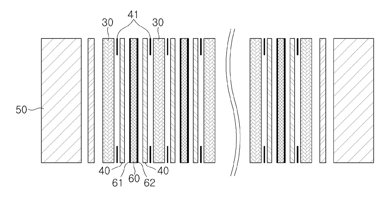
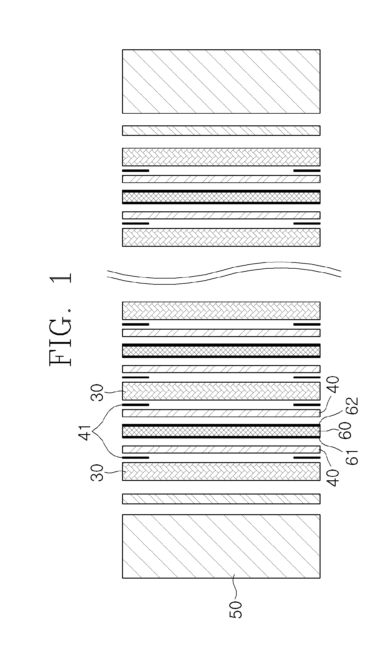
In recent years, in order to lower the electric contact resistance of the separation plate 30, the surface of the separation plate 30 is subjected to a flame treatment or a plasma treatment to expose carbon materials (carbon fibers), but there is a problem in that the carbon materials constituting the separation plate 30 are damaged.

Method used


Image

  • Composite Material Separation Plate for Fuel Cell and Method for Manufacturing Same
  • Composite Material Separation Plate for Fuel Cell and Method for Manufacturing Same
  • Composite Material Separation Plate for Fuel Cell and Method for Manufacturing Same

Examples


first embodiment

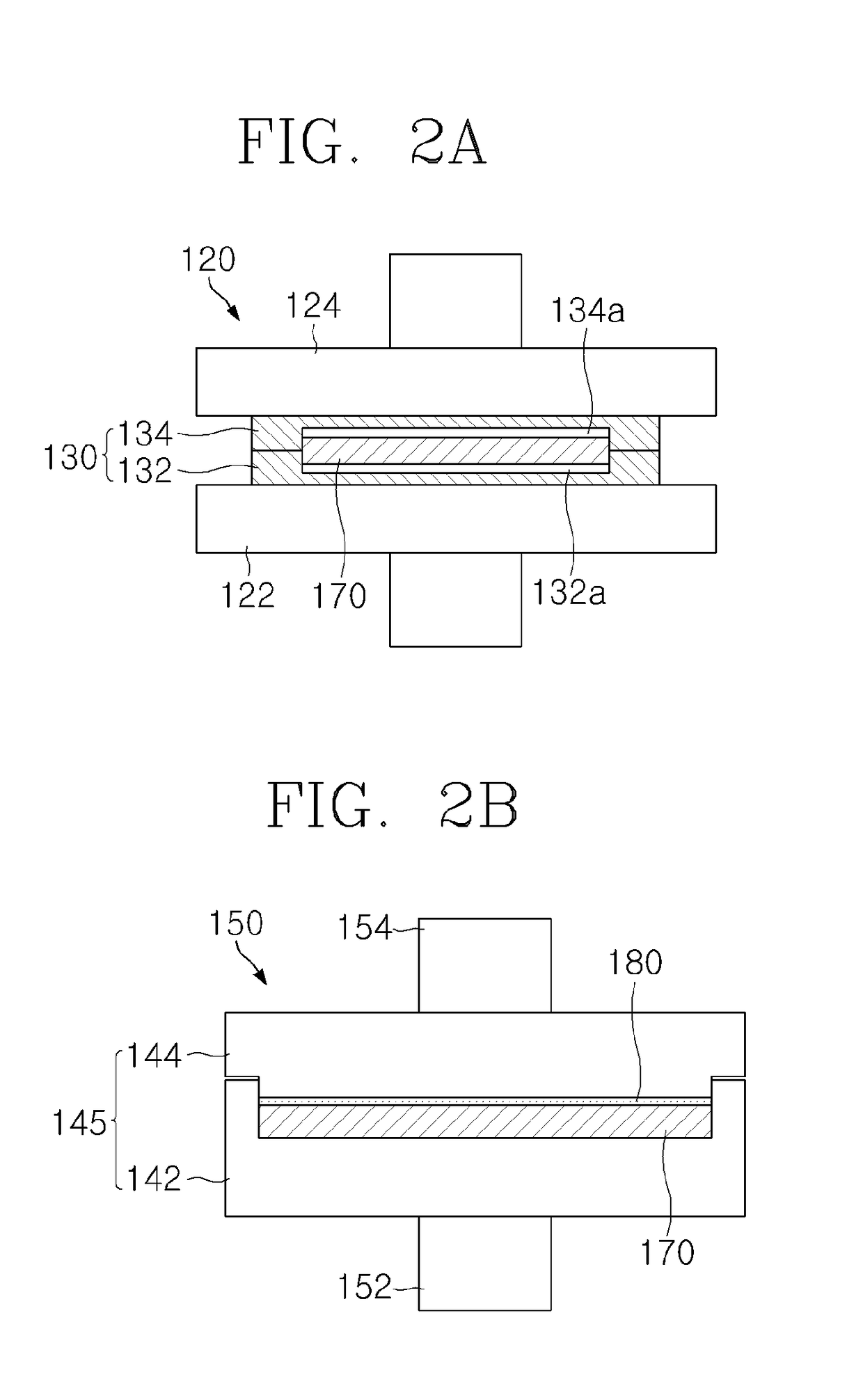
[0110]Since the process for manufacturing the preliminary separation plate is the same as the process described in the first embodiment, a separation plate manufacturing process in which regions having different electric contact resistance are formed in the separation plate by using the sacrificial layer will now be primarily described.

[0111]Referring to FIGS. 4 to 6B, in the process for manufacturing a composite material separation plate for a fuel cell according to the second embodiment of the present invention, when the preliminary separation plate 170 is completed, a second trimming machine 300 enters the preliminary separation plate 170 as described in the first embodiment of the present invention.

[0112]The second trimming machine 300 includes a third table 302, a third ram 304, and a second trimming mold assembly 330. The second trimming mold assembly 330 includes a second trimming lower mold 312 and a second trimming upper mold 314 that are seated on the third table 302.

[0113...

second embodiment

[0118]That is, in the present invention, the sacrificial layer 380 is formed only in a region corresponding to the first region 324a of the second trimming upper mold 314 or has a rectangular plate shaped sheet structure corresponding to the first region 324a.

[0119]The material of the sacrificial layer 380 has the characteristic described in the first embodiment and may adopt a polymer resin such as polyethylene or polypropylene, an elastomer such as silicone or rubber, or a polytetrafluoroethylene (PTFE) film or a silicon sheet.

[0120]When the preliminary separation plate 170 and the sacrificial layer 380 are disposed in the second trimming lower mold 312 as described above, the second trimming machine 300 is operated to perform the consolidation and curing processes of the second trimming upper mold 314 of the second trimming mold assembly 330 toward the second trimming lower mold 312.

[0121]The process of consolidating the sacrificial layer 380 may be performed by pressing the sec...


PUM

PropertyMeasurementUnit
temperatureaaaaaaaaaa
radiusaaaaaaaaaa
conductiveaaaaaaaaaa

Abstract

The present invention discloses a composite material separation plate for a fuel cell and a method for manufacturing the same. The disclosed composite material separation plate for a fuel cell according to the present invention is a composite material separation plate for a fuel cell including carbon materials covered with a polymer matrix, and is characterized in that the carbon materials are exposed to the surface of the composite material separation plate. Therefore, the present invention is advantageous in that the physical contact between a sacrificial layer, which is made of a soft material, and the separation plate exposes the carbon materials of the separation plate, thereby lowering the electric contact resistance of the separation plate.

Description

CROSS-REFERENCE TO RELATED APPLICATION[0001]This application claims priority to Korean Patent Application No. 10-2015-0066124 filed May 12, 2015, the disclosure of which is hereby incorporated in its entirety by reference.TECHNICAL FIELD[0002]The present invention relates to a composite material separation plate for a fuel cell and a method for manufacturing the same, and more particularly, to a composite material separation plate for a fuel cell and a method for manufacturing the same in which performance of the fuel cell is improved by reducing electric contact resistance of a separation plate without damage to carbon materials.BACKGROUND ART[0003]Fuel cells are energy conversion devices that directly convert chemical energy generated by oxidation of fuel into electrical energy. The fuel cells have been developed in various forms and structures depending on the type of fuel used in a cell. A polymer electrolyte membrane fuel cell (PEMFC) uses a polymer membrane having a hydrogen i...

Claims


Application Information

Patent Timeline
Patent Type & Authority Applications(United States)
IPC IPC(8): H01M8/0213
CPCH01M8/0213B82Y30/00B82Y40/00H01M8/0221H01M8/0226Y02E60/50Y02P70/50
Inventor LEE, DAI GILLEE, DONG YOUNGLIM, JUN WOOCHOE, JAE HEONKIM, MIN KOOKNAM, SOO HYUN
Owner KOREA ADVANCED INST OF SCI & TECH
Learn More