Cleaning device

a vacuum cleaner and cleaning device technology, applied in the field of vacuum cleaners, can solve the problems of user difficulty in emptying and operating the compaction mechanism, vacuum cleaners may move or topple, etc., and achieve the effect of more compact and portable, and more compact and portabl

Active Publication Date: 2018-05-17
BLACK & DECKER INC
View PDF4 Cites 58 Cited by
  • Summary
  • Abstract
  • Description
  • Claims
  • Application Information

AI Technical Summary

Benefits of technology

[0013]Preferably the second auxiliary handle is concealed when the removable dirt container is mounted on the housing. This means that at least one of the auxiliary handles does not stick out when the dirt container is mounted on the vacuum cleaner. This makes the vacuum cleaner more compact and portable.
[0014]Preferably the housing comprises a latch mechanism for releasing the dirt container from the housing. In this way the dirt container is selectively releasable and the latch mechanism prevents the dirt container from accidentally being removed from the vacuum cleaner.
[0015]Preferably the latch mechanism comprises a spring biased hook configured to engage the first auxiliary handle when the removable dirt container is mounted on the housing. This provides a dual use to the first auxiliary handle and means that the vacuum cleaner can be more compact and portable.
[0016]Preferably the vacuum cleaner comprises a dirt separator mounted in the dirt container located in an air flow path between the dirty air inlet and the motor fan assembly. By mounting the dirt separator in the dirt container, the vacuum cleaner is more compact and portable.
[0017]Preferably the moveable dirt compactor sweeps a surface of the dirt separator when the moveable dirt compactor moves from the stowed position to the dirt compacting position. Preferably the moveable dirt compactor engages an inner surface of the dirt container. This means that the dirt separator is cleaned after every compaction operation and the air flow through the dirt separator is more efficient.
[0018]Preferably one end of the dirt container comprises a door for emptying the dirt container. Preferably the dirt container comprises a first latch for releasing the door. Preferably the door comprises a detent for maintaining the door in an open position. This means that emptying the dirt container is easier when the user grips the vacuum cleaner over a bin or trash can.

Problems solved by technology

Periodically the dirt container must be emptied and this can be an undesirable task for the user.
A problem with the compaction mechanisms is that a user may have difficulty emptying and operating the compaction mechanism particularly if the user is operating the vacuum cleaner in a confined space.
Furthermore the vacuum cleaner may move or topple over if the user attempts to operate the compaction mechanism in an awkward position.

Method used


Image

  • Cleaning device
  • Cleaning device
  • Cleaning device

Examples


Embodiment Construction

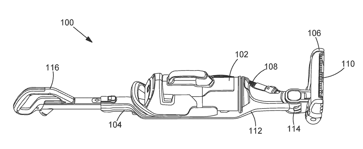
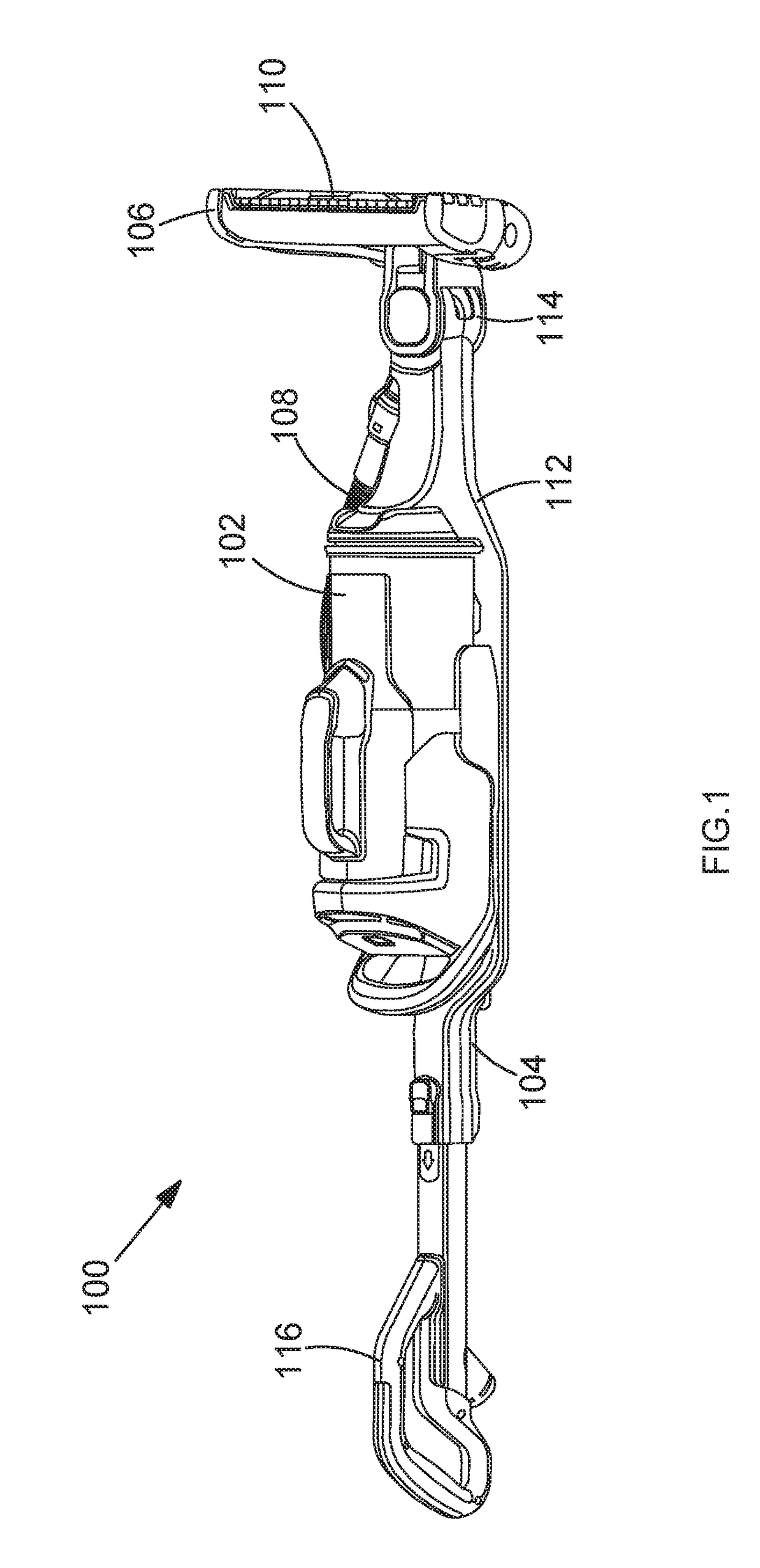
[0026]FIG. 1 shows a perspective view of a vacuum cleaner 100. The vacuum cleaner 100 comprises a vacuum cleaner unit 102 which is mounted in a chassis 104. The chassis 104 is optional. In this way the vacuum cleaner 100 is a stickvac type vacuum cleaner. In other embodiments the vacuum cleaner 100 can be any type of vacuum cleaner such as an upright vacuum cleaner, a canister vacuum cleaner or a handheld vacuum cleaner.

[0027]The chassis 104 comprises a floorhead 106 for engaging surfaces to be cleaned. The floorhead 106 has a floorhead dirty air inlet 110 which is in fluid communication with a hose 108 of the vacuum cleaner unit 102. The floorhead 106 is coupled to the chassis body 112 via an articulated joint 114. The articulated joint 114 permits the floorhead 106 to move with respect to the chassis body 112 in two degrees of freedom. The articulated joint 114 comprises two pivoting joints which have pivoting axes perpendicular to each other. The chassis also comprises a handle 1...


PUM


Abstract

A vacuum cleaner comprises: a housing and a motor fan assembly mounted in the housing, the motor fan assembly arranged to generate an air flow. A removable dirt container is mountable on the housing and in fluid communication with a dirty air inlet and the motor fan assembly. A moveable dirt compactor is mounted in the dirt container and moveable between a stowed position and a dirt compacting position wherein the moveable dirt compactor is closer to one end of the dirt container in the dirt compacting position than in the stowed position. Wherein the dirt container comprises a primary handle for actuating the moveable dirt compactor with a first hand and a first auxiliary handle for allowing the user to grip with a second hand.

Description

CROSS-REFERENCE TO RELATED APPLICATION[0001]This application claims priority to European Patent Application No. 16199418.1 filed Nov. 17, 2016. The entire contents of that application are expressly incorporated herein by reference.FIELD OF THE INVENTION[0002]The present invention relates to a vacuum cleaner. In particular the present invention relates to improved dust container capacity.BACKGROUND OF THE INVENTION[0003]Vacuum cleaners typically have an on board dirt container for receiving and storing dirt and debris that has been sucked up from a surface that is being cleaned. Periodically the dirt container must be emptied and this can be an undesirable task for the user. It is known to increase the volume of the dirt container by providing a compaction mechanism in the dirt container. Examples of compaction mechanisms are shown in EP 1 671 569 and US 2008 / 0263815. This squashes the contents of the dirt container and increases the effective volume of the dirt container and means t...

Claims


Application Information

Patent Timeline
Patent Type & Authority Applications(United States)
IPC IPC(8): A47L9/10A47L5/28A47L5/22A47L9/28A47L9/24A47L9/16A47L9/14A47L9/32
CPCA47L9/108A47L5/28A47L5/225A47L9/2857A47L9/242A47L9/1683A47L9/149A47L9/325A47L9/32
Inventor MUIR, DEREKWALKER, ANDREWGRAY, CAVANRICHARDSON, JACK
Owner BLACK & DECKER INC
Why Eureka
Try Eureka