Dual Side-Hook Structure

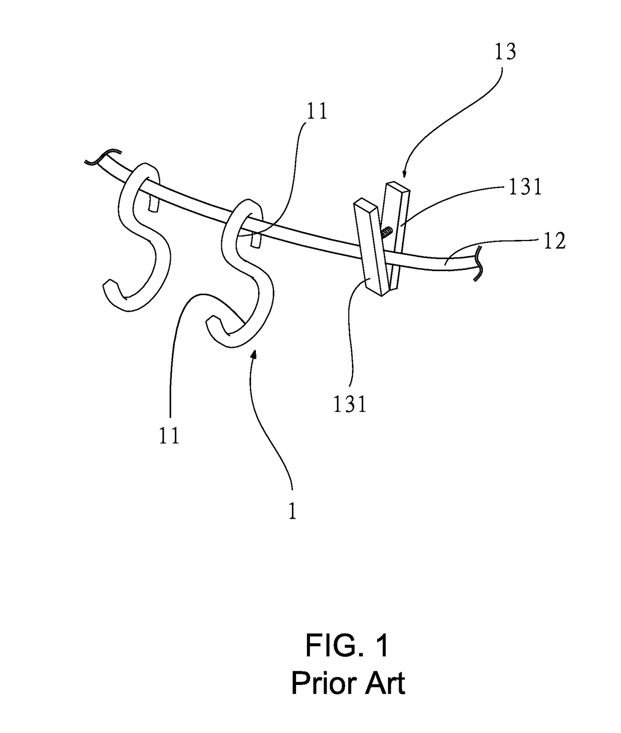
a side-hook and hook technology, applied in the direction of traveling carriers, mechanical equipment, ropes and cables for vehicles/pulleys, etc., can solve the problems of s-shaped hooks b>1/b> being shifted to the inclined end, affecting clothes or objects, and not being secured on a fixed point, etc., to achieve stably latched, facilitate hanging up objects, and stable positioning

Active Publication Date: 2018-05-17
CHEN ZHENGXIAN
View PDF13 Cites 4 Cited by
  • Summary
  • Abstract
  • Description
  • Claims
  • Application Information

AI Technical Summary

Benefits of technology

[0005]The present invention is to provide a dual side-hook structure which is primarily a hook unit with four hooks and can be stably latched on a horizontal, vertical or inclined rope or a long strip object without shifting, to facilitate hanging up an object without limitation in space. The hook unit is constituted by positioning hooks and hanging hooks which can be used interchangeably according to the thickness of the rope or the long strip object, allowing a user to choose the positioning hooks or the hanging hooks to position the hook unit. The positioning hooks are formed on a left and right side at an upper end of the hook unit, whereas the hanging hooks are formed on a left and right side at a lower end of the hook unit. The rope is enabled to pass through the positioning hooks or the hanging hooks at two ends of the hook unit to clamp the rope by the positioning hooks or the hanging hooks, thereby securing the hook unit on a fixed point on the rope without sliding freely. In addition, edges of the positioning hooks and the hanging hooks are formed with abutting devices to prevent the rope from sliding out of the rope. On the other hand, at least a side on an outer wall of the positioning hook is provided with a groove to hold the rope, allowing the rope to be stably positioned on the hook unit, which is very easy and convenient in use.
[0006]Upon using the dual side-hook structure of the

Problems solved by technology

Furthermore, if the rope 12 itself is inclined to an end, then the entire S-shaped hook 1 will be shifted to the inclined end and cannot be secured on a fixed point.
Therefore, it is rather tedious to use the S-shaped hook 1.
Thus, it is time and labor consuming, and it will result in an unrecoverable clamp mark on the clamped clothes or object, thereby damaging the clothes or object.
Furthermore, as the clamp 13 is usually made of plastic, the spring will drop out and the clipping

Method used


Image

  • Dual Side-Hook Structure
  • Dual Side-Hook Structure
  • Dual Side-Hook Structure

Examples


Embodiment Construction

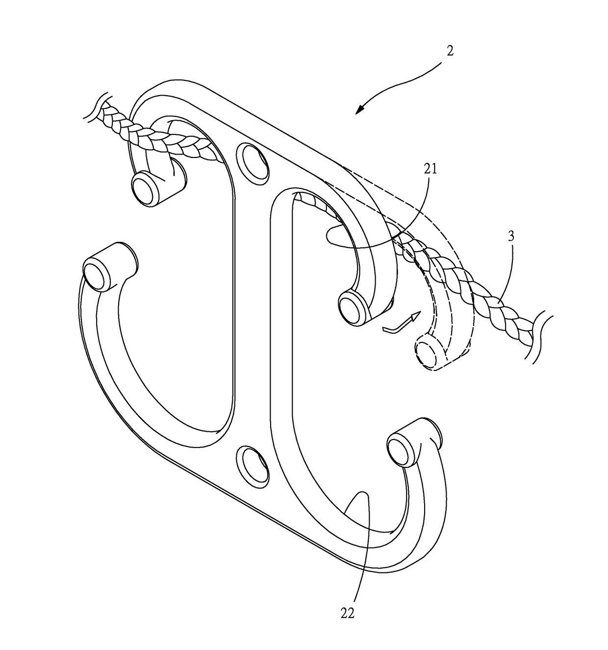
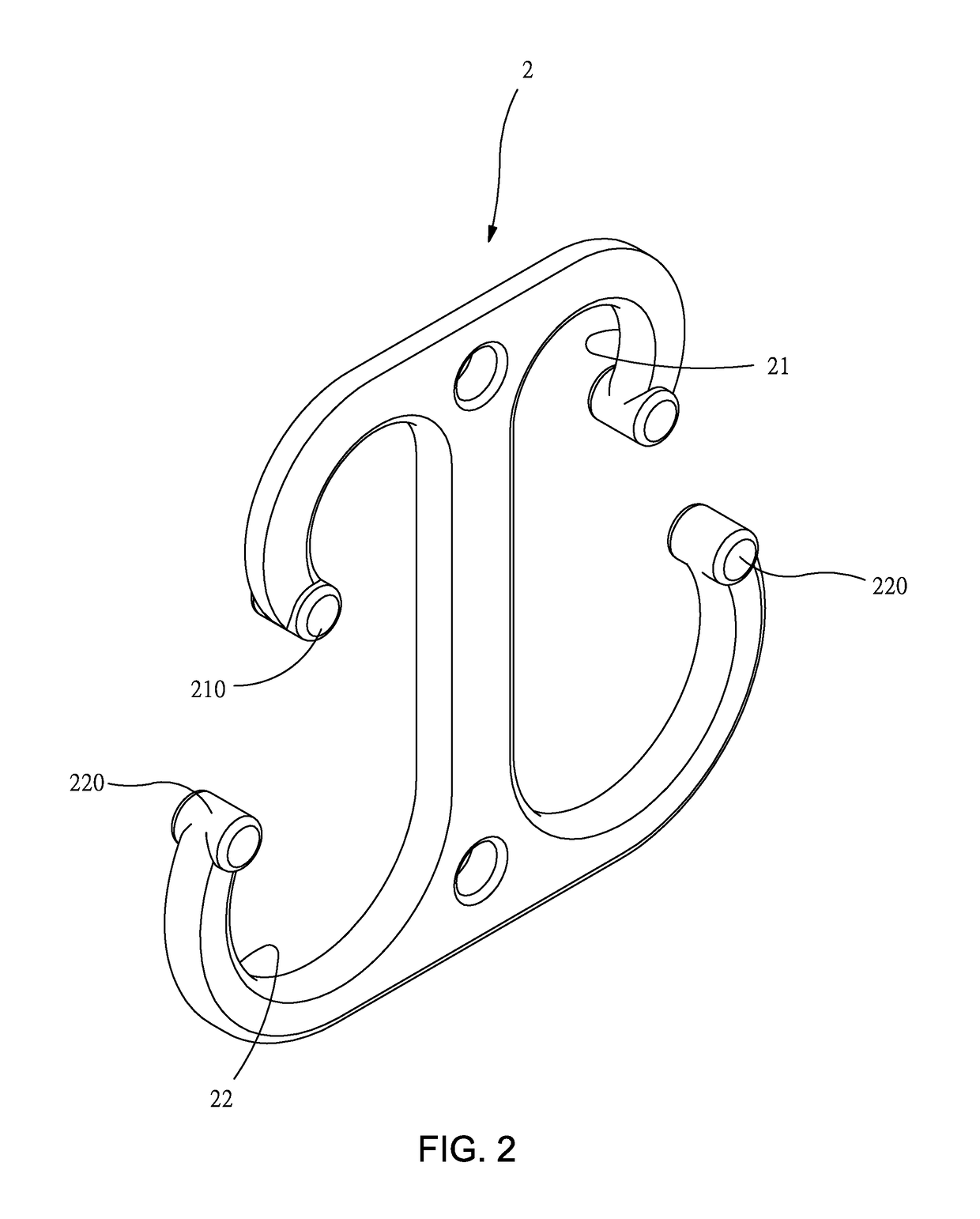
[0024]First of all, referring to FIG. 2, it shows a three-dimensional view of the present invention which is a hook unit 2 formed primarily by positioning hooks 21 and hanging hooks 22. The positioning hooks 21 are formed on a left and right side at an upper end of the hook unit 2, whereas the hanging hooks 22 are formed on a left and right side at a lower end of the hook unit 2. Edges of the positioning hooks 21 and hanging hooks 22 are provided respectively with abutting devices 210, 220 which are able to stop a wire segment, so that the wire segment will not slide out of the edges of the hook unit 2 and can be abutted in the abutting devices 210, 220 without getting loose. Therefore, the effect of stopping the wire segment can be achieved. On the other hand, the hook unit 2 can be also provided with other devices, as long as that the effect of hooking the wire segment can be achieved in a simple shape.

[0025]Secondly, as shown in FIG. 3, it shows a schematic view of operation of u...


PUM


Abstract

A dual side-hook structure is a hook unit with four hooks. The hook unit is latched on a horizontal, vertical or inclined rope or a long strip object without shifting to hang up an object without limitation in space. The hook unit includes positioning hooks on an upper end of the hook unit and hanging hooks on a lower end of the hook unit. A rope is enabled to pass through the positioning hooks or hanging hooks at two sides of the hook unit, and then the hook unit is secured on a fixed point on the rope without sliding freely. Edges of the positioning hooks and hanging hooks include abutting devices to prevent the rope from sliding out of the hook unit. The hook unit is positioned on a vertical rope by using the hanging hooks horizontally. The positioning hooks and the hanging hooks are used interchangeably. The entire hook unit is used very flexibly and versatilely without limitation in space, and is especially usable in a wild field, an outdoor area or a camping ground.

Description

FIELD OF THE INVENTION[0001]The present invention relates to a dual side-hook structure, and more particularly to a dual side-hook structure which can be used conveniently on a horizontal, vertical or inclined rope to hang up an object freely.BACKGROUND[0002]A conventional hook is an S-shaped hook 1, as shown in FIG. 1. The S-shaped hook 1 is constituted by two side-hook portions 11, with their openings being disposed upside down. Therefore, the side-hook portions 11 with different openings can be used to hang up an object. The application of the S-shaped hook 1 is very broad, such as in drying clothes, in camping or on an advertisement banner. However, when the S-shaped hook 1 is hung up on a rope 12, as there is no acting point to the S-shaped hook 1, the S-shaped hook 1 will slide freely on the rope 12. Furthermore, if the rope 12 itself is inclined to an end, then the entire S-shaped hook 1 will be shifted to the inclined end and cannot be secured on a fixed point. Therefore, it...

Claims


Application Information

Patent Timeline
IPC IPC(8): F16G11/14F16B45/00
CPCF16G11/143F16B45/00A45F2003/001A45F3/00A45F5/102A47G25/08A47J45/02A47G25/325
Inventor SHEN, ZHENGXIANXU, KEXINCHEN, XINGHANCHEN, PINSHU
Owner CHEN ZHENGXIAN
Why Eureka
Try Eureka