Drill rod or adaptor with strengthened spigot coupling

a technology of spigot coupling and adaptor, which is applied in the direction of drilling pipes, screw threaded joints, mechanical equipment, etc., can solve the problems of spigot stress in the threaded section of the male spigot, typical bending force on the joint during drilling, and breakage within the threaded portion of the joint, so as to reduce the stress of the threaded section and minimise the risk of coupling failure

Active Publication Date: 2018-05-17
SANDVIK INTELLECTUAL PROPERTY AB
View PDF7 Cites 2 Cited by
  • Summary
  • Abstract
  • Description
  • Claims
  • Application Information

AI Technical Summary

Benefits of technology

[0004]It is an objective of the present invention to provide a drill string component to form part of a drill string having a male end configured to withstand non-symmetrical loading forces acting on the drill string to reduce stress of the threaded section of the male end and minimise the risk of failure of the coupling. It is a further objective to provide a coupling that is resistant to bending waves in the drill string resultant for example from hole deviation or non-central strikes by the drive piston at the rearwardmost drill rod or shank adaptor. It is a further objective to provide a drilling component for shoulder contact coupling having a male threaded end that provides a secure coupling with a corresponding female threaded end of a neighbouring drill rod or other component of the drill string so as to form an integral and secure unit within the assembled drill string.

Problems solved by technology

When the male and female threaded ends of neighbouring drill rods are coupled to create the drill string, the joint is typically subjected to bending forces during drilling.
These bending moments fatigue the coupling and lead to breakage within the threaded portion of the joint.
In particular, stresses in the threaded section of the male spigot are typically considerable and it is common for the spigot to fail at the region of the threads.
Additionally, stresses at the region of the threads occur also due to the transmission of the compressing shock wave.

Method used


Image

  • Drill rod or adaptor with strengthened spigot coupling
  • Drill rod or adaptor with strengthened spigot coupling
  • Drill rod or adaptor with strengthened spigot coupling

Examples


Embodiment Construction

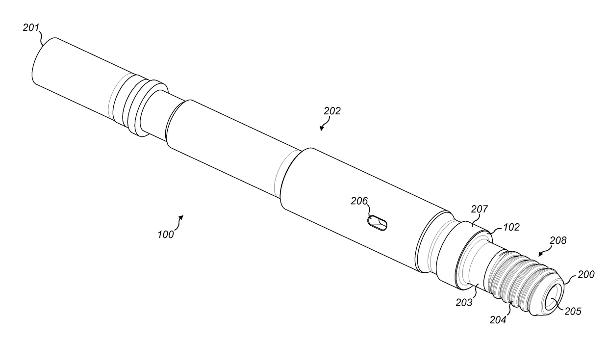
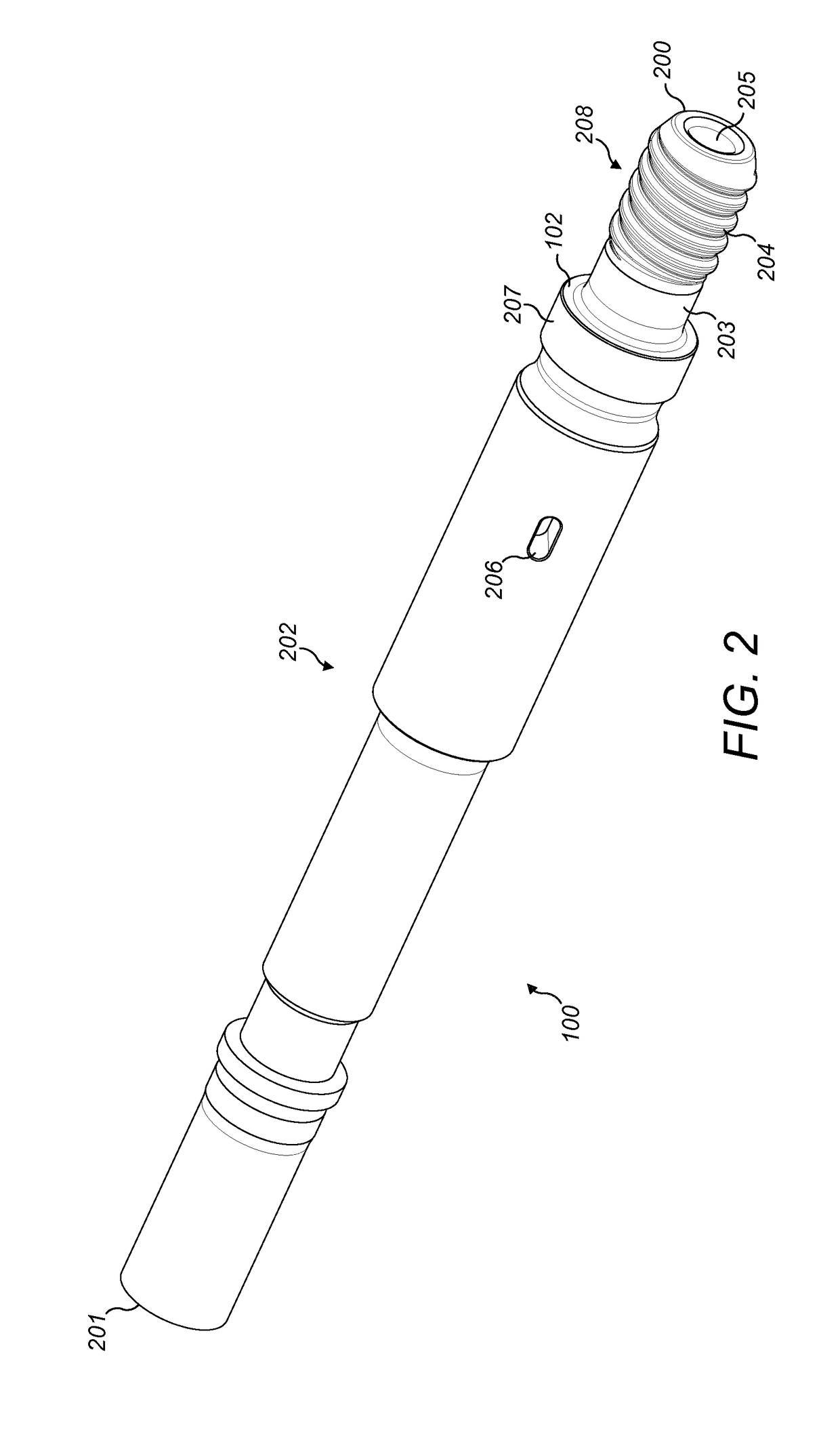
[0027]The subject invention will be described by way of example with reference to a shank adaptor being a drill string component to form part of a drill string. It will be appreciated that the subject invention is applicable to any elongate component having a shoulder contact male spigot end adapted to form a coupling joint with a threaded female sleeve of an adjacent component of the drill string. Accordingly, the subject invention may be applied to a drill rod, drill tubing, a shank, a shank adaptor, a drill bit, a shaft or adaptor mounted at the driving end of the drill string or at the bit end of the drill string.

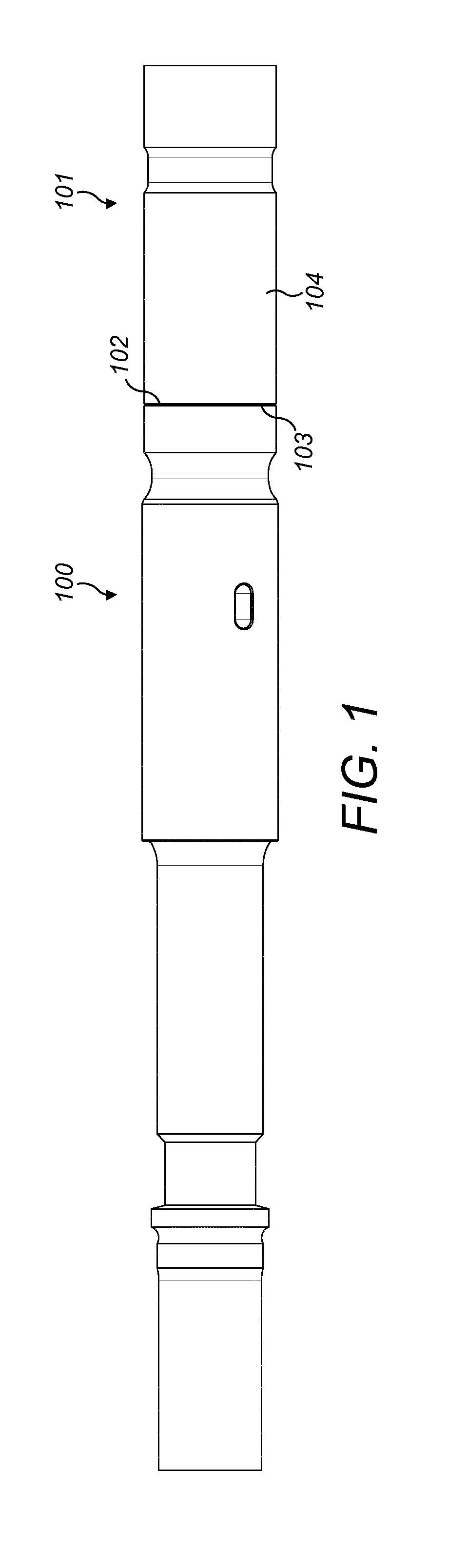
[0028]Referring to FIG. 1, a drill string comprises an elongate shank adaptor 100 coupled axially to an endmost drill rod 101 via a threaded coupling 104 formed by a male threaded end of the shank adaptor 100 and a female threaded end of the drill rod 101. Both drill string components 100, 101 are coupled via ‘shoulder contact’ in which an annular side surface 102 of th...


PUM


Abstract

An elongate component, such as a drill rod or adaptor, forms part of a drill string having a shoulder contact male spigot coupling. The male spigot includes a non-threaded shank and a threaded section in which an axial length of the non-threaded shank is provided at a predetermined minimum relative to an outside diameter of the spigot at the threaded section.

Description

FIELD OF INVENTION[0001]The present invention relates to a drill string component to form part of a drill string having a male spigot coupling end with a threaded section configured to minimise stress at the region of the threads and failure of the coupling.BACKGROUND ART[0002]Percussion drilling is used to create a long borehole via a plurality of elongate drill string rods coupled together end-to-end by interconnected male and female threaded ends. The well-established technique breaks rock by hammering impacts transferred from the rock drill bit, mounted at one end of the drill string, to the rock at the bottom of the borehole. Typically, the energy required to break the rock is generated by a hydraulically driven piston that contacts the end of the drill string (via a shank adaptor) to create a stress (or shock) wave that propagates through the drill string and ultimately to the base rock level. Conventional male and female threaded couplings are described in EP 2845993, EP 1259...

Claims


Application Information

Patent Timeline
Patent Type & Authority Applications(United States)
IPC IPC(8): F16L15/06E21B17/042
CPCF16L15/06E21B17/042E21B1/00E21B17/0426E21B1/38
Inventor AHOLA, PETRIWICKSTROM, DAVIDNORMAN, ANDREAS
Owner SANDVIK INTELLECTUAL PROPERTY AB
Why Eureka
Try Eureka