Lighting device, projector, display system, and light source adjustment method

a technology of light source adjustment and projector, which is applied in the direction of color television details, instruments, projectors, etc., to achieve the effect of accurate adjustment of color balan

Active Publication Date: 2018-05-17
SHARP NEC DISPLAY SOLUTIONS LTD
View PDF2 Cites 11 Cited by
  • Summary
  • Abstract
  • Description
  • Claims
  • Application Information

AI Technical Summary

Benefits of technology

[0017]The present invention provides a lighting device, a projector provided with this lighting device, and a light source adjustment method of the lighting d

Problems solved by technology

However, this correction method entails the problems described below because the luminance of the first blue semiconductor laser is adjusted such that the light quantities of

Method used


Image

  • Lighting device, projector, display system, and light source adjustment method
  • Lighting device, projector, display system, and light source adjustment method
  • Lighting device, projector, display system, and light source adjustment method

Examples


first example embodiment

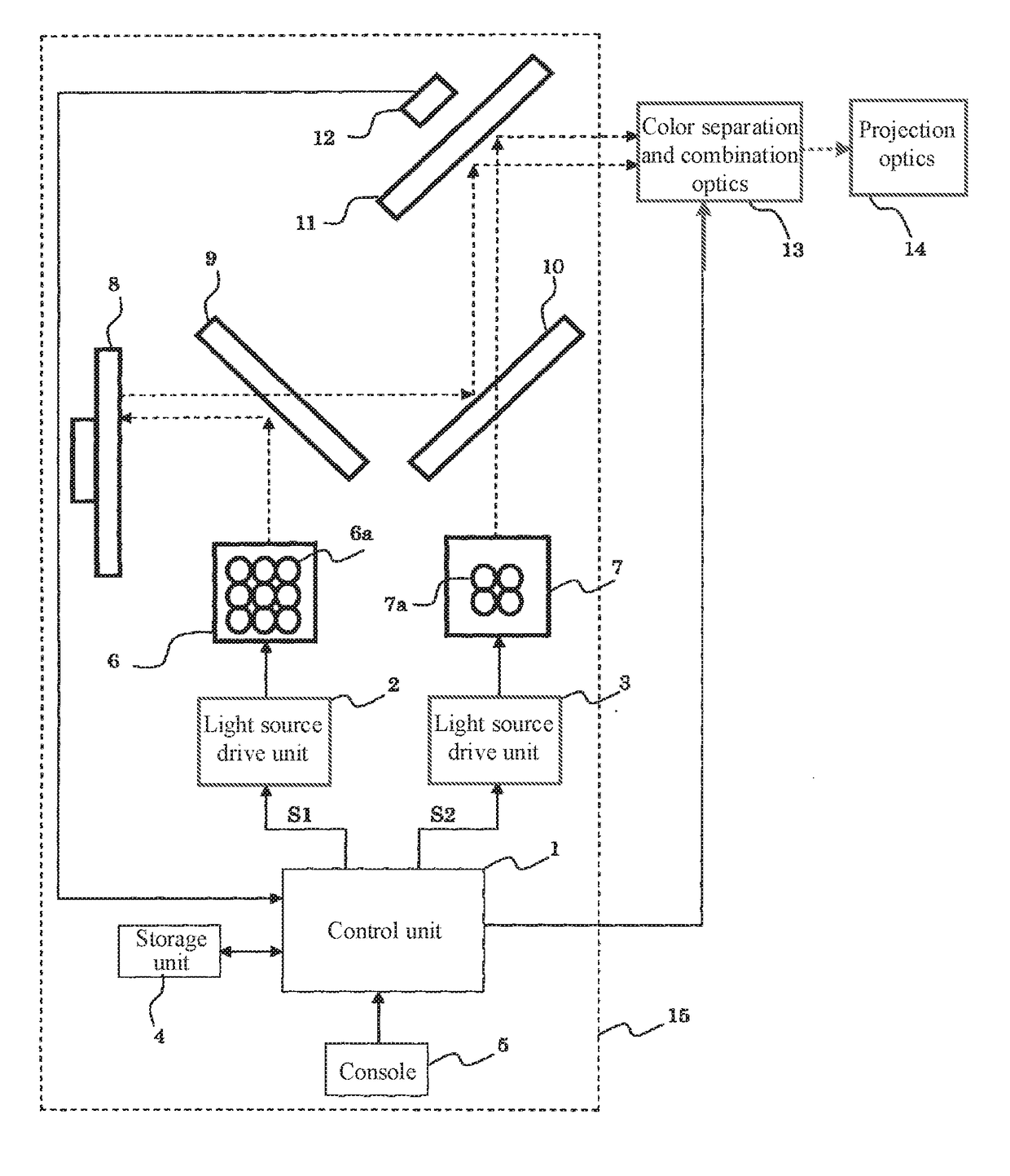
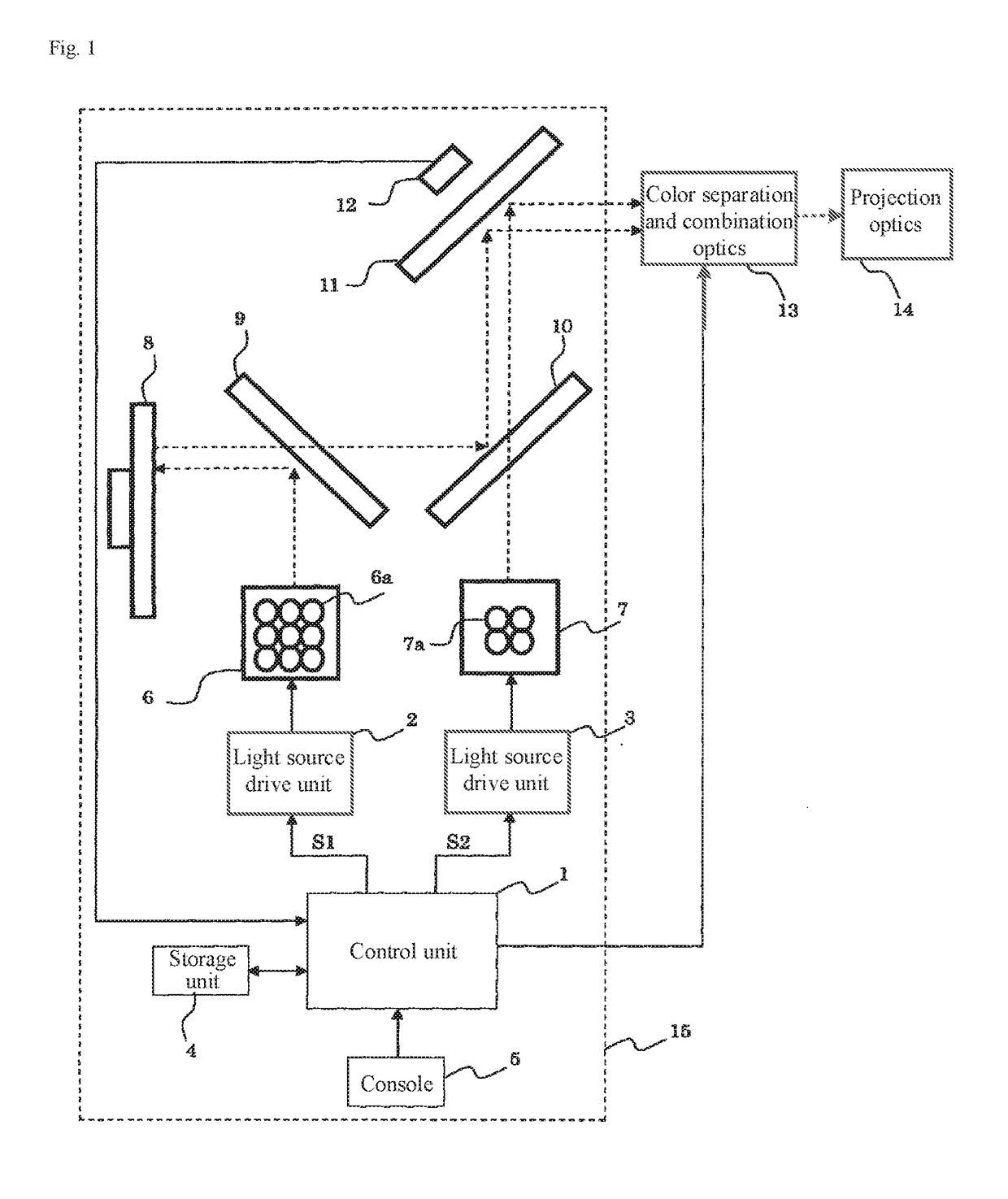
[0054]FIG. 1 is a block diagram showing the configuration of a projector that is provided with a lighting device that is the first example embodiment of the present invention.

[0055]Referring to FIG. 1, the projector includes lighting device 15, color separation and combination optics 13, and projection optics 14.

[0056]Color separation and combination optics 13 includes a color separation unit, first to third display elements, and a color combination unit. A color separation unit, which is a component that separates white light that is the output light of lighting device 15 into red light, green light, and blue light, is made up of a plurality of dichroic mirrors, a lens group, and a mirror.

[0057]Display panels such as liquid crystal display elements or digital micromirror devices (DMD) can be used as the first to third display elements. The first display element modulates red light to form a red image. The second display element modulates green light to form a green image. The third...

second example embodiment

[0099]FIG. 4 is a schematic view showing the configuration of a display system that has a plurality of projectors provided with lighting devices that are the second example embodiment of the present invention.

[0100]Referring to FIG. 4, the display system includes four projectors 100-103. Projectors 100 and 101 are capable of intercommunication by way of communication cable 104. Projectors 101 and 102 are capable of intercommunication by way of communication cable 105. Projectors 102 and 103 are capable of intercommunication by way of communication cable 106. Wired / Wireless LAN, RS232C, and DDC / CI (Display Data Channel Command Interface) may also be applied to communication among projectors 100-103. Each of projectors 100-103 holds in advance address information required for intercommunication. In other words, projectors 100-103 are each able to communicate with each other.

[0101]Projector 100 projects upper left screen 200, projector 101 projects upper right screen 201, projector 102...


PUM


Abstract

A lighting device includes: a first light source that supplies yellow fluorescent light; a second light source that supplies blue light; a light sensor that detects the light quantity of a blue component of combined light, in which the yellow fluorescent light and blue light have been combined, and the light quantity of a first color component that is contained in the yellow fluorescent light and that differs from the blue component; and a control unit that adjusts the luminance of the first and second light sources. The control unit acquires each of a first light quantity that is the light quantity of the first color component and a second light quantity that is the light quantity of the blue component in a first state in which the first light source is ON and the second light source is OFF, and acquires a third light quantity.

Description

TECHNICAL FIELD[0001]The present invention relates to a lighting device that employs a phosphor as a light source, a projector that is provided with the lighting device, and a light source adjustment method of the lighting device. The present invention further relates to a display system that uses the projector.BACKGROUND ART[0002]Patent Document 1 discloses a projector that is provided with a lighting device that employs a phosphor as a light source.[0003]The lighting device includes a first blue semiconductor laser, a second blue semiconductor laser, a dichroic mirror, a phosphor wheel, a wavelength selection wheel, and a rod integrator. The first blue semiconductor laser supplies first blue light (excitation light) having a wavelength of approximately 450 nm. The second blue semiconductor laser supplies second blue light (illumination light) having a wavelength of approximately 460 nm.[0004]The first blue light supplied from the first blue semiconductor laser is incident to one s...

Claims


Application Information

Patent Timeline
IPC IPC(8): G03B21/20H04N9/31
CPCG03B21/2053H04N9/3194G03B21/204G03B21/2066G03B21/208G03B21/2013G03B21/206H04N9/3147H04N9/3158H04N9/3161H04N9/3182H05B45/22H05B47/165H05B47/17
Inventor KOBAYASHI, HIROYUKIKATO, TSUTOMU
Owner SHARP NEC DISPLAY SOLUTIONS LTD
Why Eureka
Try Eureka