

Transient overvoltage protection system
a protection system and transient overvoltage technology, applied in emergency protection arrangements for limiting excess voltage/current, emergency protection arrangements for automatic disconnection, electrical equipment, etc., can solve the problems of components coming to the end of their life and difficult to ensure the reliability of disconnection produced by melting of thermofusible elements
- Summary
- Abstract
- Description
- Claims
- Application Information
AI Technical Summary
Benefits of technology
Problems solved by technology
Method used
Image

Examples
first embodiment
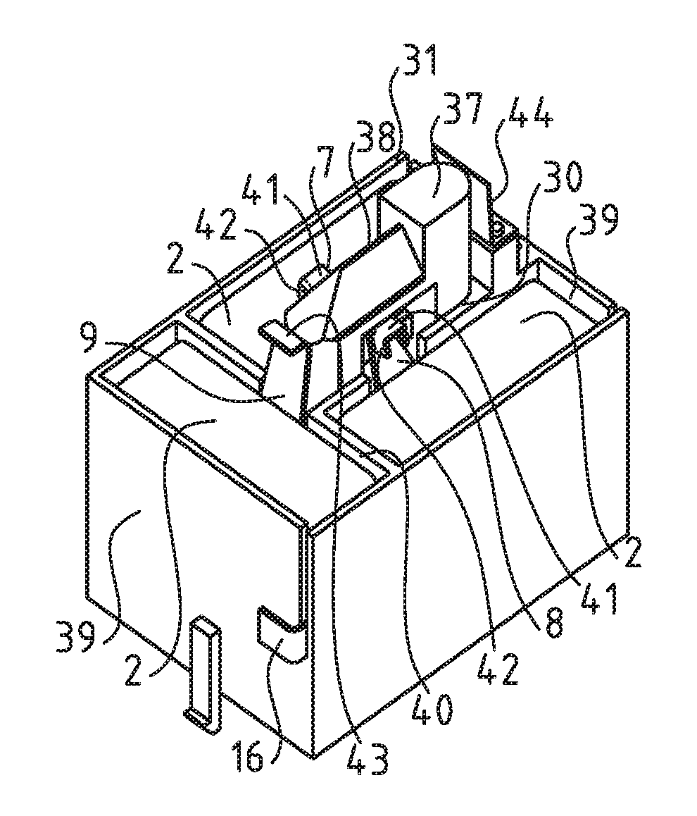
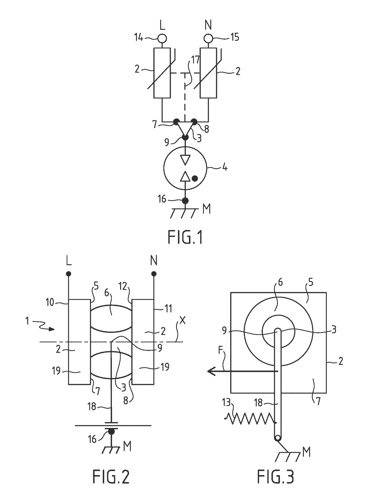
[0070]The electrical diagram of a protection device 1 according to the invention will be described in relation to FIG. 1. The device 1 comprises a gas discharge arrestor 4 having a first electrical terminal 16 and a second electrical terminal 9. The device 1 further comprises a first varistor having a first electrical terminal 7 and a second electrical terminal 14, as well as a second varistor 2 having a first electrical terminal 8 and a second electrical terminal 15.
[0071]The discharge arrestor 4 and the two varistors 2 are connected to one another by one of their electrical terminals so as to form an electrical Y connection. More specifically, the first electrical terminal 16 of the discharge arrestor 4 is connected to the ground M and the respective first electrical terminals 14, 15 of the varistors 2 are respectively connected to an electrical terminal L and an electrical terminal N intended to connect two electrical lines of the circuit or electrical equipment item to be protec...
second embodiment
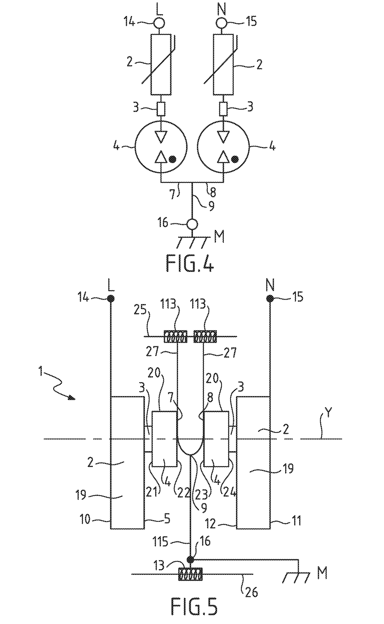
[0090]the invention will be presented with reference to FIGS. 4 and 5.
[0091]The electrical diagram of a protection device 1 according to the second embodiment of the invention will be described in relation to FIG. 1.
[0092]The device 1 comprises two assemblies each consisting of a discharge arrestor 4 and a varistor 2 in series. In each assembly, the varistor 2 and the discharge arrestor 4 are connected electrically via a thermofusible braze 3. The discharge arrestor 4 is also fixed mechanically to the varistor 2 by the thermofusible braze 3.
[0093]The first assembly has a first electrical terminal 14 and a second electrical terminal 7. The second assembly has a first electrical terminal 15 and a second electrical terminal 8.
[0094]The first electrical terminals 14 and 15 of the varistors 2 are respectively connected to an electrical terminal L and an electrical terminal N intended to connect two electrical lines of the circuit or electrical equipment item to be protected.
[0095]The sec...
third embodiment
[0114]The electrical diagram of a protection device 1 according to the invention will be described in relation to FIG. 6. The device 1 comprises a discharge arrestor 4 having a first electrical terminal 16 and a second electrical terminal 9. The device 1 further comprises a varistor 2 having a first electrical terminal 7 and a second electrical terminal 14. The device 1 also comprises an electricity-conducting branch 28 having a first electrical terminal 15 and a second electrical terminal 8.
[0115]The discharge arrestor 4, the varistor 2 and the electricity-conducting branch 28 are connected to one another by one of their electrical terminals so as to form a Y-shaped electrical diagram. More specifically, the first electrical terminal 16 of the discharge arrestor 4 is connected to the ground M and the first electrical terminal 14 of the varistor 2 is connected to an electrical terminal L. The first electrical terminal 15 of the electricity-conducting branch 28 is connected to an ele...
PUM
 Abstract
Description
Claims
Application Information