System for protecting an object from fire

Inactive Publication Date: 2016-10-27
INFERNOSHIELD
View PDF2 Cites 2 Cited by
  • Summary
  • Abstract
  • Description
  • Claims
  • Application Information

AI Technical Summary

Benefits of technology

[0050]In one form, the surface may be chosen from any surface that may be subject to a heat source. In one form, the surface may be subject to the threat of a forest fire. In this form, the surface may be a surface on a living organism such as a plant, grass, tree or the like, or the surface may be on a non-living item such as a fence, house, wall, roof or other man-made structure. In this form, the thermal insulating layer applied to one or more of these sur

Problems solved by technology

However to date many parts of the world are still subject to the devastating effects of forest fires on a frequent basis.
However, it has been shown that regular burning does not prevent fires altogether.
There is also a significant drawback associated with excessive greenhouse gas emissions that result from regular controlled burns.
However, during intense forest fires, water does not function as a significant fire retardant and evaporates quickly as soon as the temperature surrounding the property increases.
It is also difficult to locate sufficient quantities of wat

Method used


Image

  • System for protecting an object from fire
  • System for protecting an object from fire
  • System for protecting an object from fire

Examples


example 1

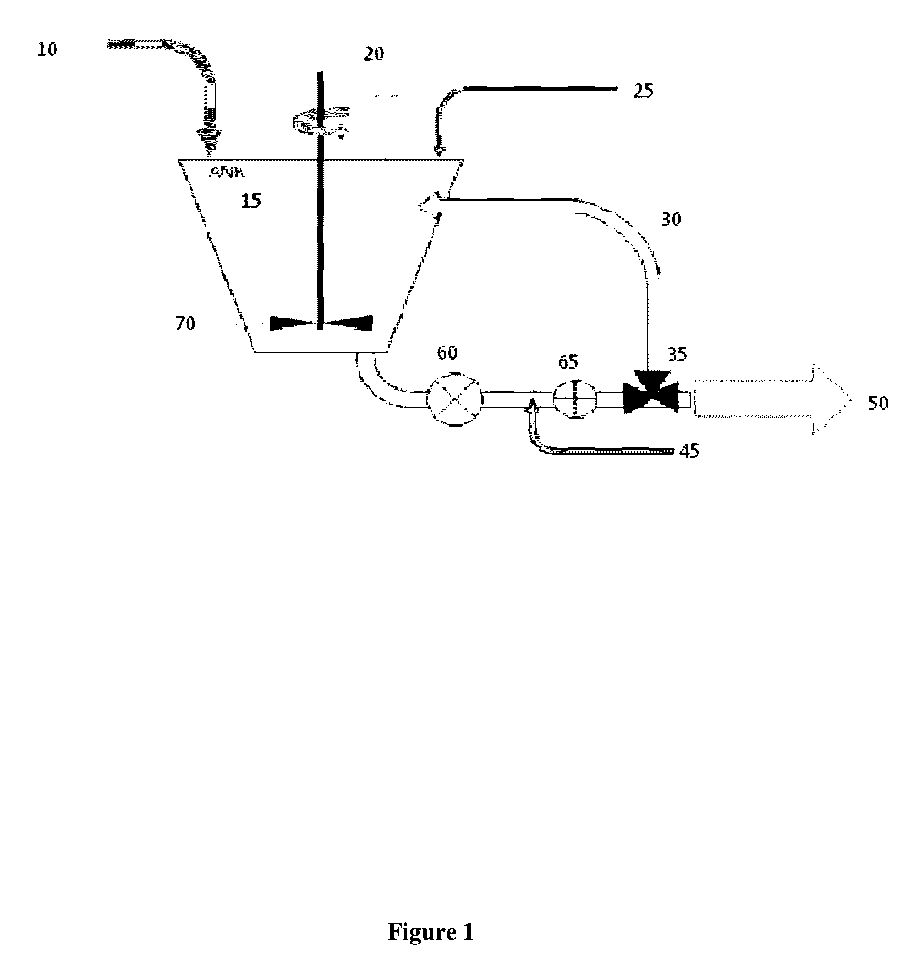
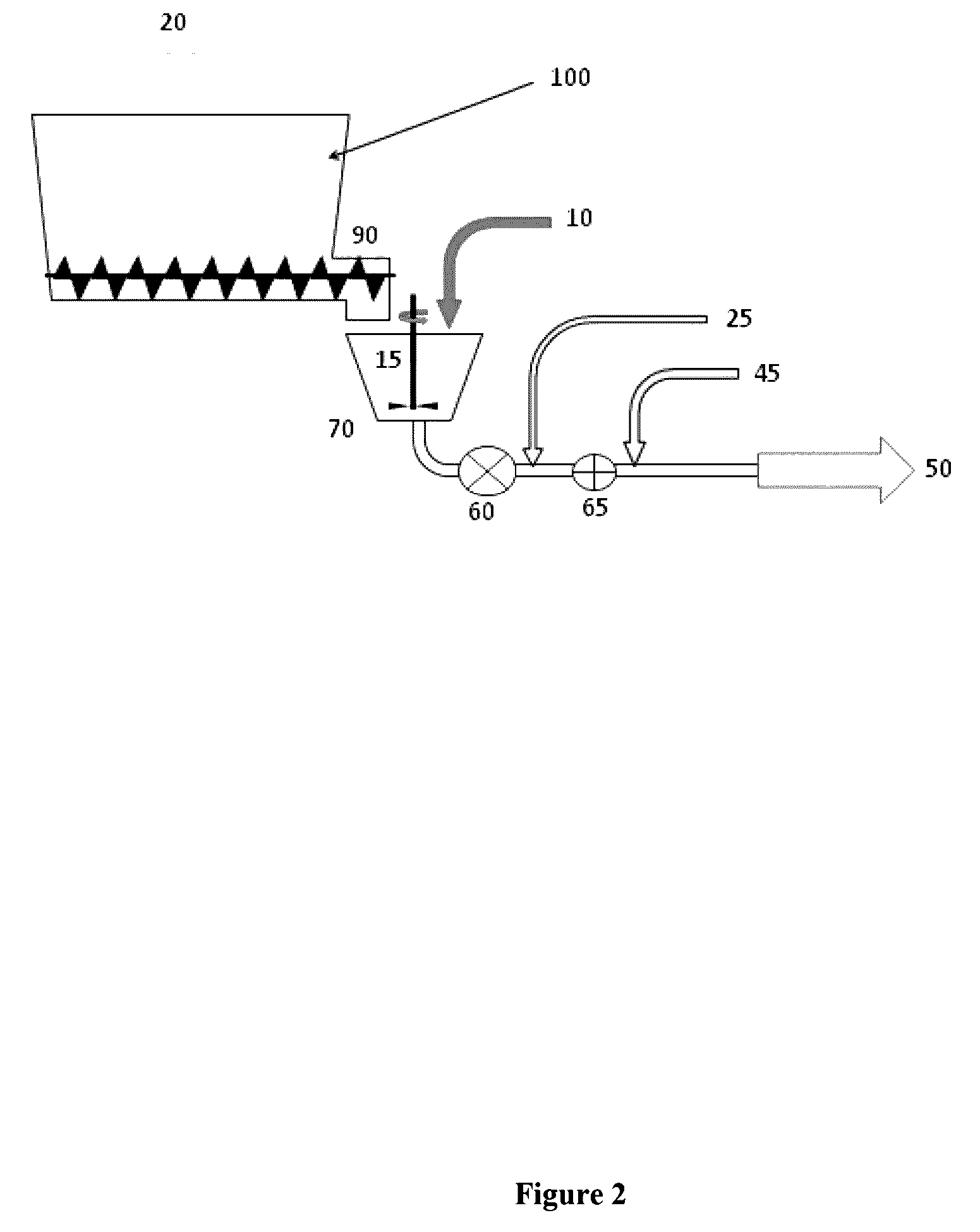
[0083]A composition including 25 litres of water, and 20 kilograms of calcium carbonate was mixed together with 600 millilitres of a foaming agent which was selected from a sulphonated anionic surfactant with a molecular weight of between 200 to 300. The subsequent mixture was then aerated until an aerated slurry was formed.

[0084]The aerated slurry was then applied to a wooden fence paling providing a layer of aerated slurry with an average thickness of 15 mm. Another control fence paling was also provided after which an oxyacetylene torch was applied to the surface of the fence paling including the layer of aerated slurry for a period of 45 seconds at a distance of 15 cm. The oxyacetylene torch was then applied to the control fence paling for 45 seconds at the same distance of 15 cm.

[0085]The aerated slurry was then washed off the first fence paling and the damage caused by the oxyacetylene torch on the two fence palings was compared. It was quite apparent that the fence paling inc...

example 2

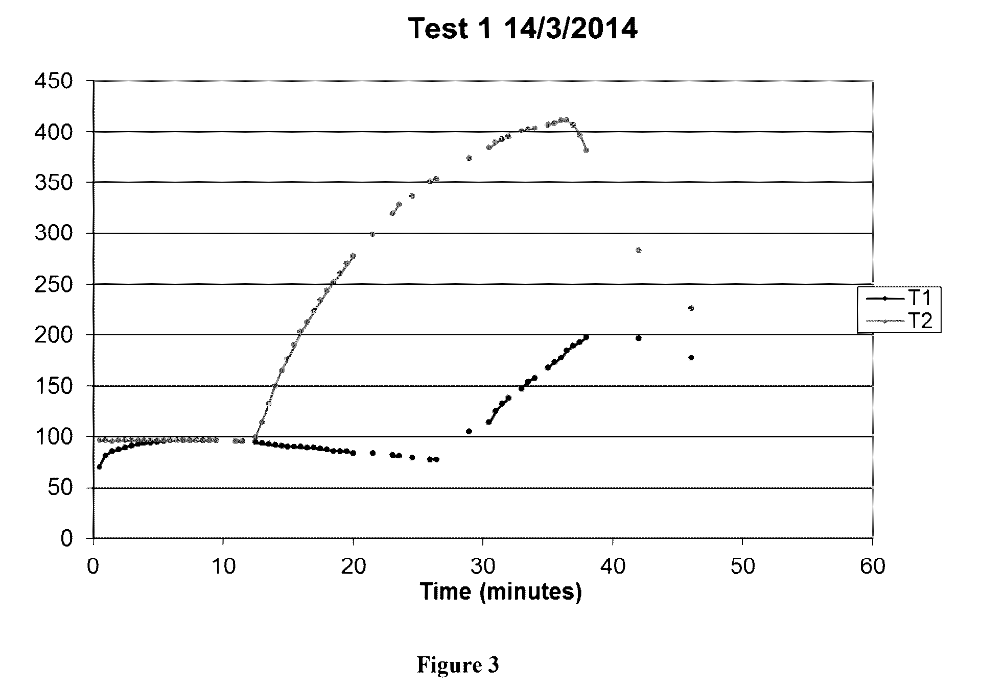
[0086]Four (4) small-scale thermal tests were conducted using a four burner gas stove. Each ring can be individually adjusted. K type Thermocouples connected to a data logger were used to record temperatures against time.

Determining Heat of Burner

[0087]To determine the heat being delivered by the gas burners, a cast iron pot was filled with 1 litre of water and placed on the burner. Only the two inner gas rings were lit.

[0088]The heat input into the water is given by:

Q=kAmΔT

[0089]Where:

[0090]Q=heat in Kj

[0091]K=specific heat=4.12 Kj / KgK for water

[0092]M=mass of water

[0093]ΔT=temperature rise

[0094]From this experiment, Q / A for the two inner rings only was found to be:

[0095]37 kW / m2

[0096]“Bushfire Attack Level” (BAL) is used to assess the intensity of radiant heat exposure as per AS3959 (Australian Standard AS3959) in relation to building practices. There are 6 levels, the highest being “BAL-FZ” which refers to the “Flame Zone”, and this corresponds to a heat load greater than 40 kW...


PUM


Abstract

A method and system for protecting an object from fire are provided. The system comprises a composition including water, a solid particulate material, and a foaming agent, the composition being aeratable to form an aerated slurry, and an apparatus to aerate the composition to form the aerated slurry and to apply the aerated slurry to the object. Upon application, the aerated slurry forms a thermally-insulating layer adapted to substantially cover a surface of the object, thereby protecting the object from fire damage. The thermally-insulating layer is further adapted to dry on the surface of the object, and whereby the thermally-insulating layer is removable from the surface of the object by application of water.

Description

CROSS-REFERENCE TO RELATED APPLICATIONS[0001]This application is a continuation-in-part of currently pending PCT Application No. PCT / AU2014 / 050299 entitled “FIRE PROTECTION COMPOSITION, USE THEREOF, AND METHOD OF PRODUCING AND APPLYING SAME” filed Oct. 22, 2014, which further claims benefit of Australia Patent Application 2013904068 filed Oct. 22, 2013, each of which is herein incorporated by reference in its entirety.BACKGROUND[0002]1. Field of the Invention[0003]The present invention relates to a system for protecting an object from fire. The system would typically include a composition which, when applied to a surface, provides a heat insulation layer and / or an oxygen barrier on the surface of the object that is capable of providing protection from fire. The present invention also relates to the use of the composition as a fire barrier, fire extinguisher and / or fire retardant. In addition, the present invention provides a process for preparing the composition; an apparatus for ap...

Claims


Application Information

Patent Timeline
IPC IPC(8): A62C5/02A62C2/00A62D1/02
CPCA62C5/022A62D1/0071A62C2/00A62C3/02C09K21/02A62C3/10
Inventor HUNTER, ANDREW DAVIDPROUD, DAVID JOHN
Owner INFERNOSHIELD
Why Eureka
Try Eureka