Wireless power feeding device, wireless power receiving device, wireless power supply system, and method for measuring current of wireless power feeding device

Active Publication Date: 2018-05-24
LAPIS SEMICON CO LTD
View PDF0 Cites 1 Cited by
  • Summary
  • Abstract
  • Description
  • Claims
  • Application Information

AI Technical Summary

Benefits of technology

[0011]According to the present invention, the composite current into which the currents outputted from the N number of switching elements connected in parallel are combined is supplied to the power transmission coil as the drive current. The current measurement resistor is connected in series to one of the N number of switching elements, and the measured current signal representing the amount of the

Problems solved by technology

However, in the above-described non-contact power supply device, since a current sensor is provided in series between a power line and a

Method used


Image

  • Wireless power feeding device, wireless power receiving device, wireless power supply system, and method for measuring current of wireless power feeding device
  • Wireless power feeding device, wireless power receiving device, wireless power supply system, and method for measuring current of wireless power feeding device
  • Wireless power feeding device, wireless power receiving device, wireless power supply system, and method for measuring current of wireless power feeding device

Examples


Example

[0022]An embodiment of the present invention will be described below in detail with reference to the drawings.

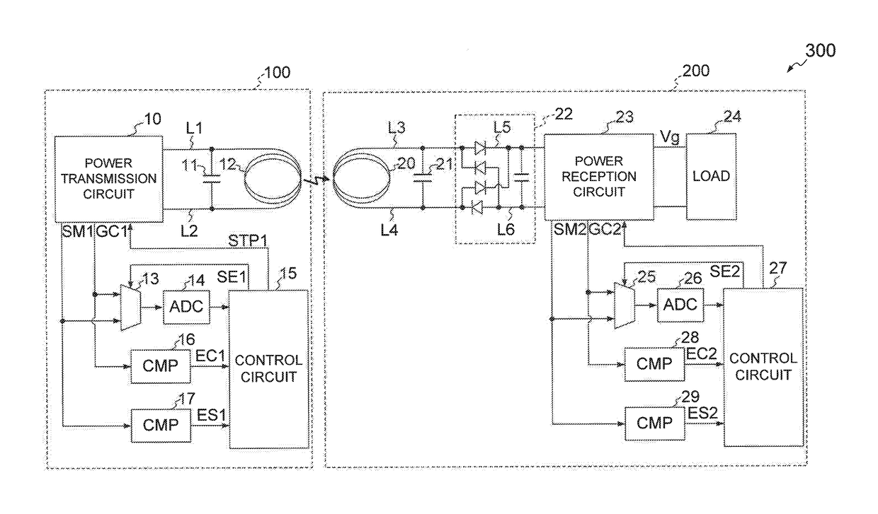
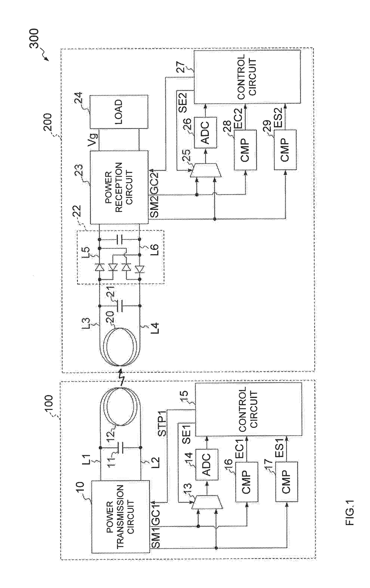
[0023]FIG. 1 is a block diagram illustrating a schematic configuration of a wireless power supply system 300 including a wireless power feeding device 100 and a wireless power receiving device 200 according to the present invention. The wireless power supply system 300 supplies power from the wireless power feeding device 100 to the wireless power receiving device 200 by magnetic coupling between a power transmission coil 12 provided in the wireless power feeding device 100 and a power reception coil 20 provided in the wireless power receiving device 200.

[0024]The internal configuration of each of the wireless power feeding device 100 and the wireless power receiving device 200 will be concretely described below in order of the wireless power feeding device 100 and the wireless power receiving device 200.

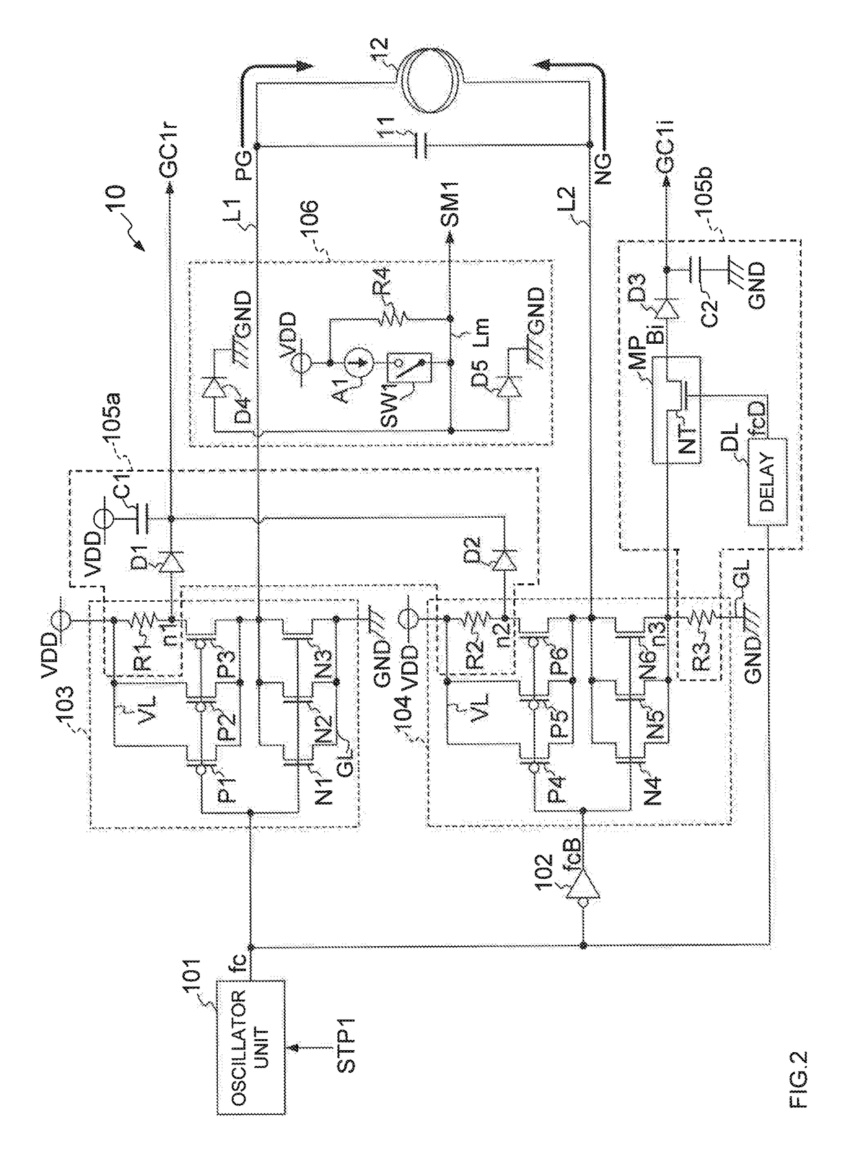
[0025][Wireless Power Feeding Device 100]

[0026]The wireless power feedi...


PUM


Abstract

A wireless power feeding device includes first to Nth (N is an integer of 2 or more) switching elements connected in parallel to each other between a power line, which is connected to one end of a power transmission coil, and a ground line, each of the first to Nth switching elements supplying a current to the drive line in accordance with an oscillation signal; a first resistor connected in series with the first switching element between the power line and the ground line; and a current measurement circuit for generating a first measured current signal representing the amount of the drive current on the basis of the potential of one end of the first resistor.

Description

BACKGROUND OF THE INVENTION1. Field of the Invention[0001]The present invention relates to a wireless power feeding device for feeding power in a non-contact manner, a wireless power receiving device for receiving power in a non-contact manner, a wireless power supply system including the wireless power feeding device and the wireless power receiving device, and a method for measuring a current of the wireless power feeding device.2. Description of the Related Art[0002]In recent years, wireless power supply systems for feeding power in a non-contact manner are proposed to supply power to wearable devices such as watches, IC (integrated circuit) cards, and the like. In the wireless power supply system, power is transmitted and received between a coil (power transmission coil) of a power transmission device and a coil (power reception coil) of a power reception device disposed oppositely.[0003]At present, various frequencies, for example, 6.78 MHz, 13.56 MHz, and the like are used as ...

Claims


Application Information

Patent Timeline
IPC IPC(8): G01R15/14H02J50/12H02H9/04G01R19/165
CPCG01R15/146H02J50/12H02H9/04G01R19/16547G01R19/0092H02J7/007192H02J7/0029G01R31/42H02J7/0031H02J50/60H02J7/00304H02J7/04
Inventor TAYA, TAKASHI
Owner LAPIS SEMICON CO LTD
Why Eureka
Try Eureka