Valve timing control apparatus for internal combustion engine and internal combustion engine using the same

Inactive Publication Date: 2018-05-31
HITACHI AUTOMOTIVE SYST LTD
View PDF3 Cites 0 Cited by
  • Summary
  • Abstract
  • Description
  • Claims
  • Application Information

AI Technical Summary

Benefits of technology

[0010]According to the one aspect of the present invention, the outer peripheral portion of the housing and the inner peripheral portion of the timing pulley are connected via the coupling beam portion

Problems solved by technology

Some of conventional valve timing control apparatuses have failed to achieve the reduction in the axial size because a timing pulle

Method used


Image

  • Valve timing control apparatus for internal combustion engine and internal combustion engine using the same
  • Valve timing control apparatus for internal combustion engine and internal combustion engine using the same
  • Valve timing control apparatus for internal combustion engine and internal combustion engine using the same

Examples


Example

First Embodiment

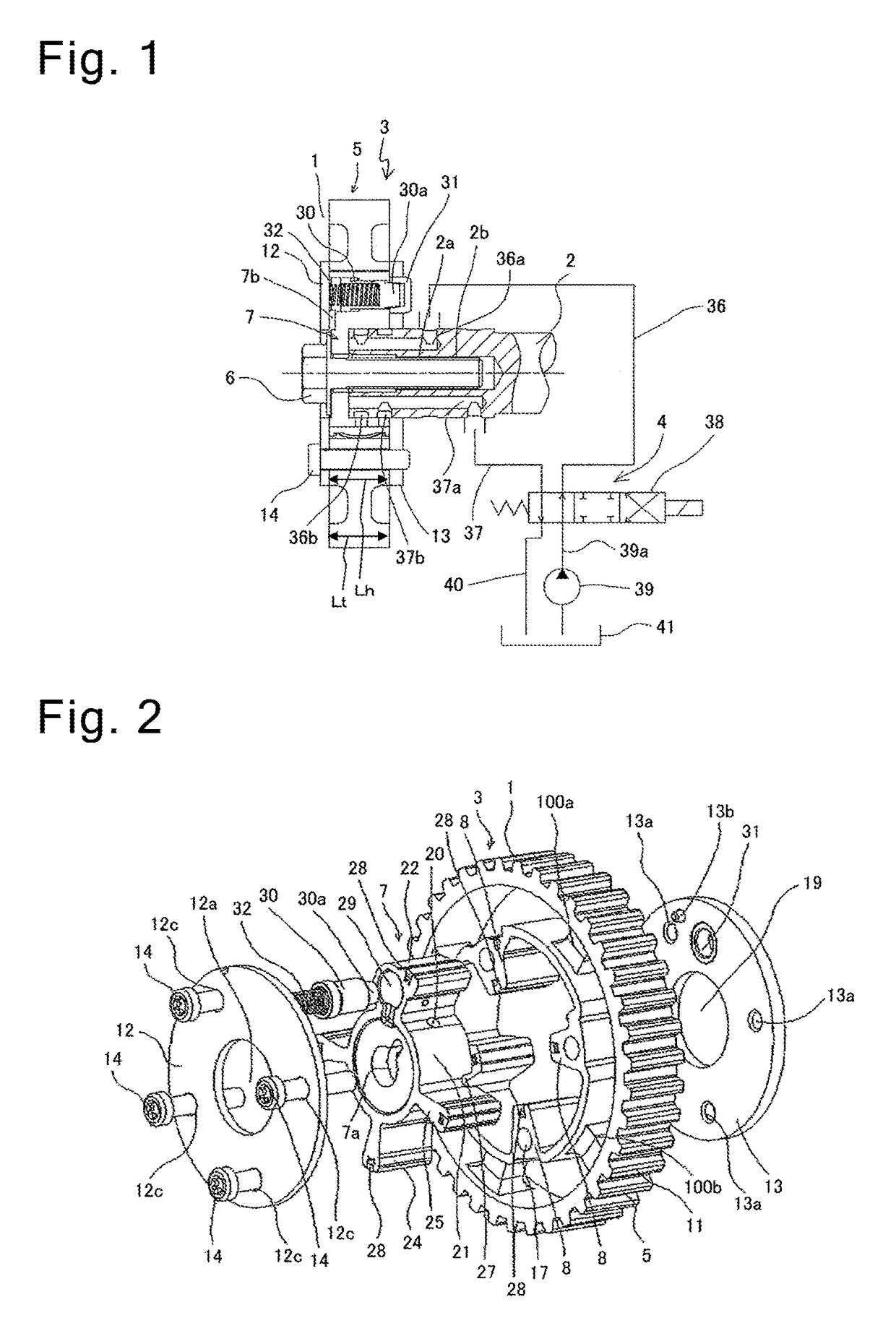
[0020]In the following description, a valve timing control apparatus for an internal combustion engine according to a first embodiment of the present invention will be described in detail with reference to FIGS. 1 to 5.

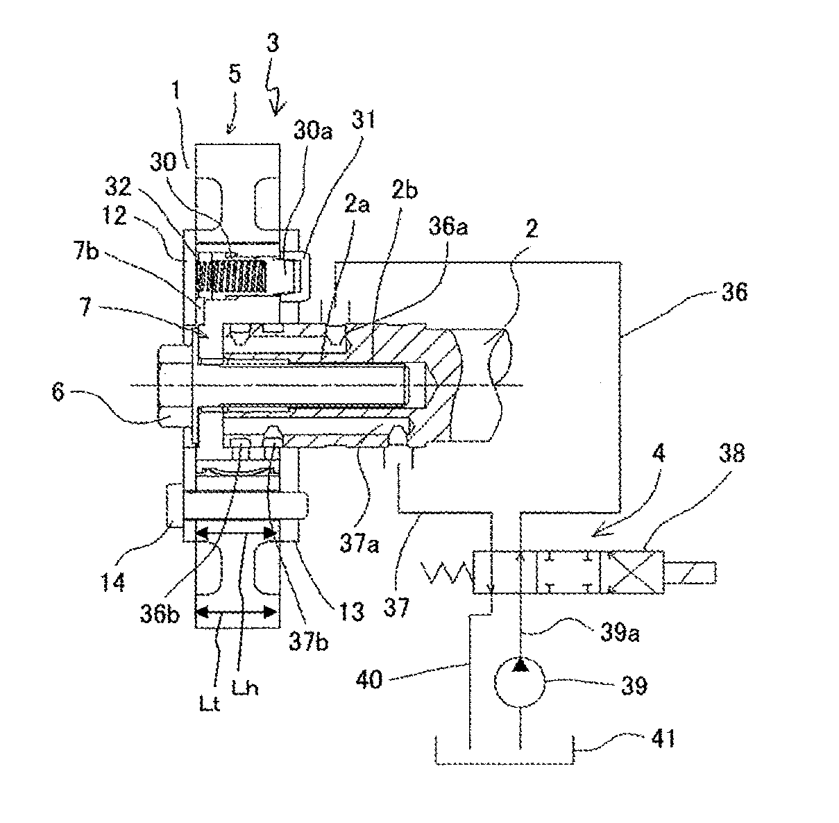
[0021]The valve timing control apparatus illustrated in FIG. 1 is disposed on an upper surface of a cylinder head of an engine, and functions to control an opening / closing timing of an engine valve. Then, the valve timing control apparatus includes a timing pulley 1, a camshaft 2, a phase conversion mechanism 3, and a hydraulic circuit mechanism 4. The timing pulley 1 is rotationally driven by a crankshaft rotatable according to activation of a not-illustrated piston of the engine via a timing belt. The camshaft 2 is provided rotatably relative to the timing pulley 1. The phase conversion mechanism 3 is disposed between the timing pulley 1 and the camshaft 2, and converts a relative rotational position between them. The hydraulic circuit mechanism 4 su...

Example

Second Embodiment

[0067]Next, a valve timing control apparatus according to a second embodiment of the present invention will be described with reference to FIGS. 6 and 7. The present embodiment is basically similar to the first embodiment, and therefore similar functions and effects to the first embodiment will not be described below.

[0068]FIG. 6 illustrates a maximum retard angle state, and FIG. 7 illustrates a maximum advance angle state. A retard angle-side stopper surface 200a and an advance angle-side stopper surface 200b are formed on both side surfaces of the vane 22 having the maximum width. Then, a retard angle-side abutment surface 300a is formed on a wall surface of a shoe 8r which the retard angle-side stopper surface 200a hits and abuts against, and an advance angle-side abutment surface 300b is formed on a wall surface of a shoe 8a which the advance angle-side stopper surface 200b hits and abuts against.

[0069]Then, when the valve member 7 is controlled to the maximum r...

Example

Third Embodiment

[0075]Next, a valve timing control apparatus according to a third embodiment of the present invention will be described with reference to FIG. 8. The present embodiment is basically similar to the first embodiment, and therefore similar functions and effects to the first embodiment will not be described below.

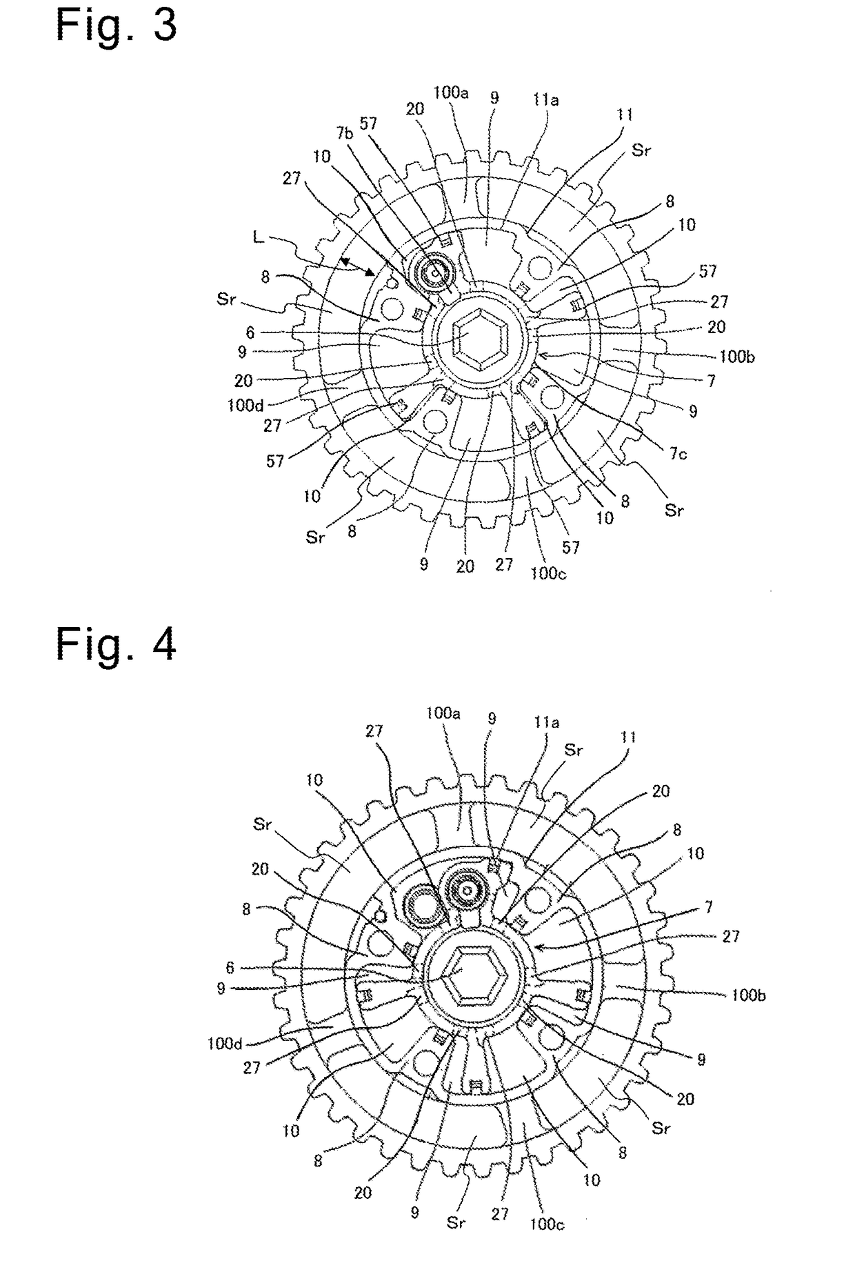
[0076]In the present embodiment, the coupling beam portions 100a to 100d are disposed at positions where the individual shoes 8 formed on the housing main body 11 and the timing pulley 1 face each other as illustrated in FIG. 8. In other words, the coupling beam portions 100a to 100d are provided while being arranged on outer sides in the radial directions of the individual shoes 8 as indicated by an arrow A. Such a configuration is employed for the following reason.

[0077]The bolt 14 is inserted through the bolt insertion hole 17 of each of the shoes 8, and the front plate 12, the housing main body 11, and the rear plate 13 are securely fastened. Therefore, side...


PUM


Abstract

Provided is a novel valve timing control apparatus capable of reducing an axial length and of reducing a thickness of a housing. A valve timing control apparatus for an internal combustion engine includes a timing pulley to which a rotational force is transmitted from a crankshaft via a timing belt, a housing configured to be rotated by the timing pulley and including a plurality of shoes provided on an inner peripheral surface thereof, and a vane rotor relatively rotatably contained inside the housing and configured to be rotated in synchronization with a camshaft. The vane rotor includes a vane forming a retard angle oil chamber and an advance angle oil chamber inside the housing in cooperation with the plurality of shoes. A predetermined interval is provided between an outer peripheral portion of the housing and an inner peripheral portion of the timing pulley. An outer peripheral portion of a housing main body of the housing and the inner peripheral portion of the timing pulley are coupled with each other via a plurality of coupling beam portions with intervals in a circumferential direction. The housing main body, the timing pulley, and the plurality of coupling beam portions are integrally formed.

Description

TECHNICAL FIELD[0001]The present invention relates to a valve timing control apparatus that variably controls an opening / closing timing of an engine valve, which is an intake valve or an exhaust valve of an internal combustion engine, according to an operation state, and an internal combustion engine using this valve timing control apparatus.BACKGROUND ART[0002]As a conventional valve timing control apparatus, a vane-type valve timing control apparatus is well known. This vane-type valve timing control apparatus includes a housing to which a rotational force is transmitted from a crankshaft, and a vane member rotatably contained inside this housing and fixed at an end portion of the camshaft. An advance angle oil chamber and a retard angle oil chamber are formed between a plurality of shoes each protruding inward from a diameter direction on an inner peripheral surface of the housing, and a plurality of vanes of the vane member.[0003]Then, the vane-type valve timing control apparatu...

Claims


Application Information

Patent Timeline
IPC IPC(8): F01L1/356F01L1/344F01L1/053F01L1/08
CPCF01L1/356F01L1/3442F01L1/0532F01L1/08F01L2001/34426F01L2103/02F01L2001/34456F01L2001/34453F01L2303/02
Inventor WATANABE, ATSUSHI
Owner HITACHI AUTOMOTIVE SYST LTD
Why Eureka
Try Eureka