
Real-time detection system for parked vehicles

a real-time detection and parking technology, applied in the field of real-time detection systems, can solve problems such as traffic accidents, slow traffic streams, and block the sight of following vehicles, and achieve the effects of reducing computational costs, high efficiency, and reducing the probability of false alarms

Active Publication Date: 2018-05-31
UNIVERSITY OF MACAU
View PDF0 Cites 29 Cited by
  • Summary
  • Abstract
  • Description
  • Claims
  • Application Information

AI Technical Summary

Benefits of technology

The present invention is a real-time detection system for parked vehicles. The goal is to provide a straightforward and efficient detection system in real time. The system can reduce the chance of false alarms and minimize computational costs.

Problems solved by technology

Vehicles parked along the side of a road represent an important problem in traffic surveillance.
Parking a vehicle on the side of a main road can slow down traffic streams, block the sight of following vehicles and even lead to traffic accidents.
However, manually observing these surveillance video remains laborious and costly.
However, inevitably, there have been some drawbacks to the conventional background subtraction method (Liyuan et al.)
Arguably, the most serious problem is that the subtracted foreground (difference) usually contains substantial noise due to the scene background model and noise from cameras.
Moreover, the background of real-world settings may change in an outdoor scene as a result of various complicated factors, e.g., changes in illumination and new stationary foreground objects.
These factors are likely to introduce noise into the foreground mask.
Thus, the detection is equally weighted across the scene in the background subtraction stage, and it is likely that the stationary objects in the unrelated area will trigger false-positive alarms.
However, real-time performance is crippled by more complicated operations and corresponding higher computational costs.

Method used


Image

  • Real-time detection system for parked vehicles
  • Real-time detection system for parked vehicles
  • Real-time detection system for parked vehicles

Examples


Embodiment Construction

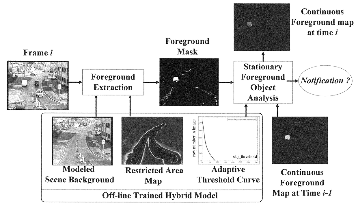
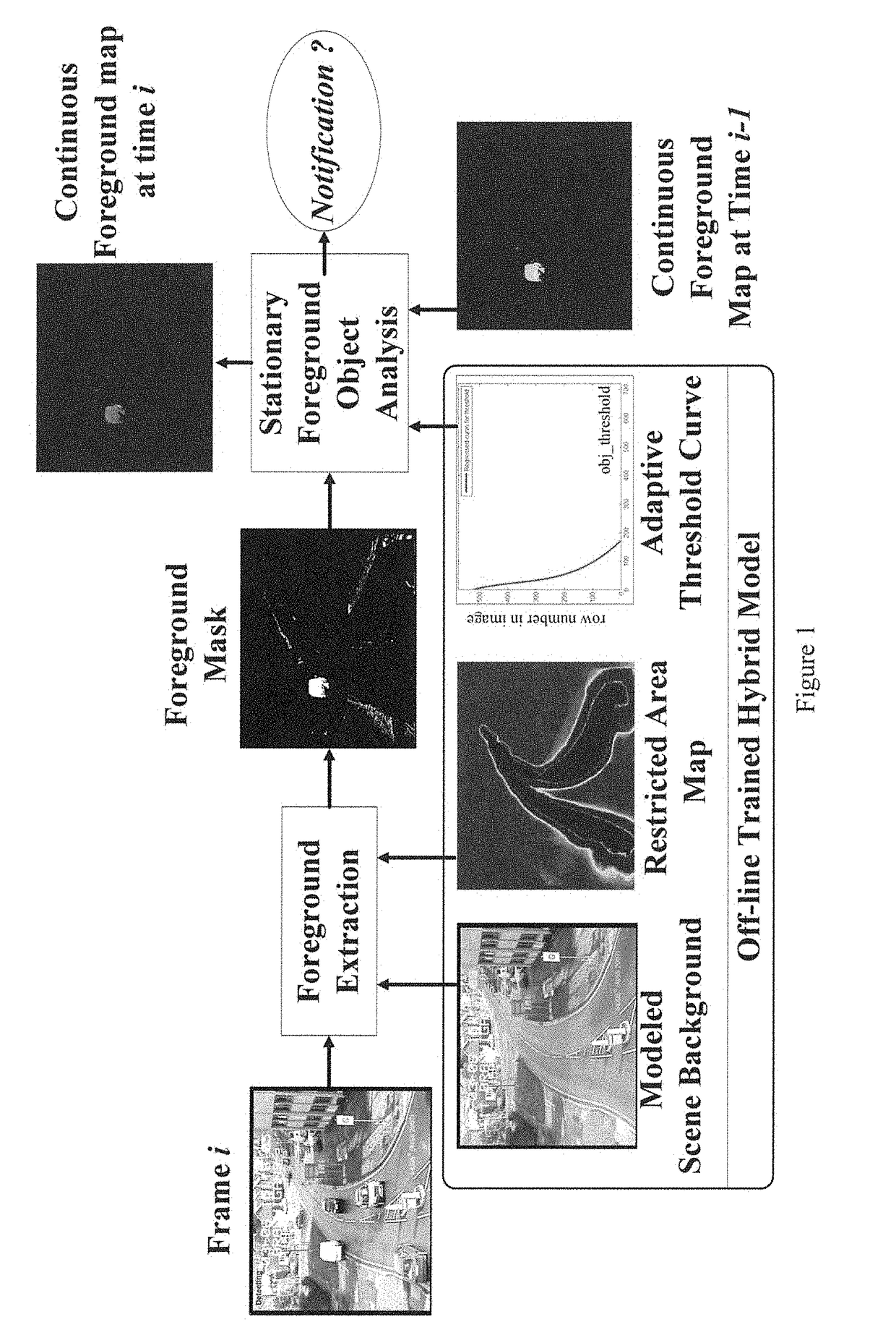
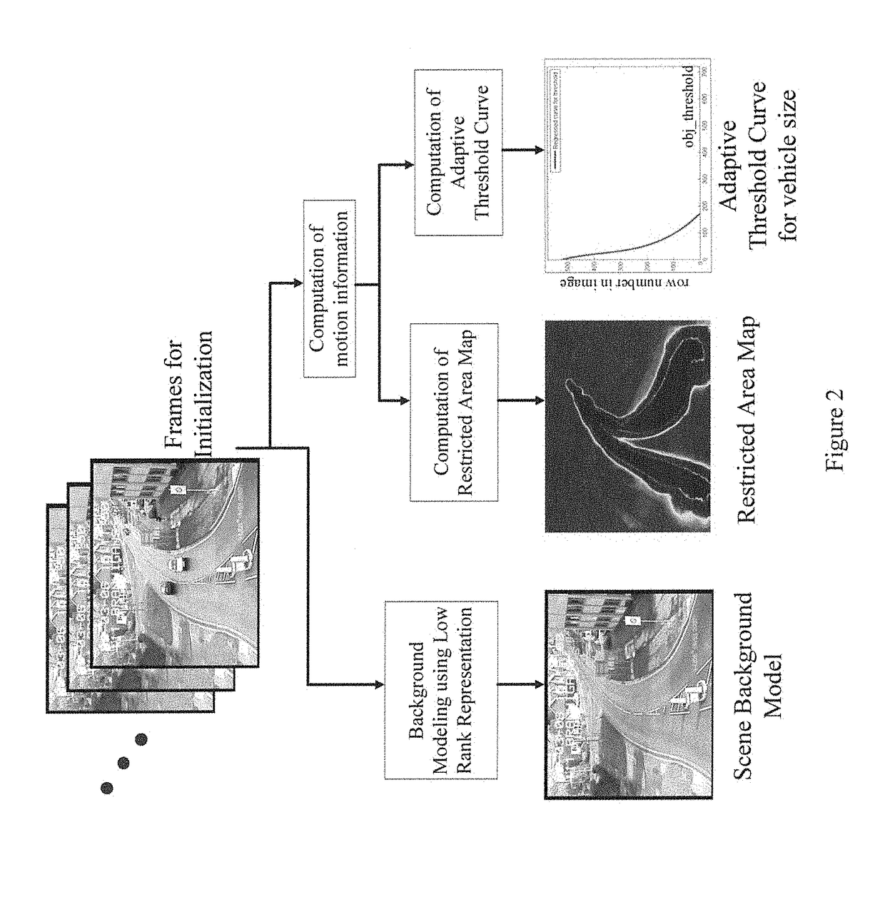
[0032]In present application, a real-time detection system for parked vehicles along the side of a road is proposed. The main idea of the present application is that the system can determine where the road is and how large the vehicles are by exploiting the motion information of normal activity in the scene; in addition, the system can further estimate the roadside and the adaptive thresholds for the vehicles. Compared to conventional parked vehicle detectors, the proposed system is capable of automatically generating the road and the restricted area along it. After the weight map of the restricted area is obtained, the system can apply it to the background subtraction process and generate a substantially clearer foreground mask that is capable of automatically ruling out unrelated foreground objects. Moreover, during initialization, the vehicle size is regressed onto a function curve that outputs adaptive thresholds for a vehicle with respect to the Y-axis. The system triggers a no...


PUM


Abstract

The present invention discloses a real-time detection system based on hybrid background modeling for detecting parked vehicles along the side of a road. The hybrid background model consists of three components: 1) a scene background model, 2) a computed restricted area map, and 3) a dynamic threshold curve for vehicles. By exploiting the motion information of normal activity in the scene, we propose a hybrid background model that determines the location of the road, estimates the roadside and generates the adaptive threshold of the vehicle size. The system triggers a notification when a large vehicle-like foreground object has been stationary for more than a pre-set number of video frames (or time). The present invention is tested on the AVSS 2007 PV dataset. The results are satisfactory compared to other state-of-the-art methods.

Description

BACKGROUND OF THE INVENTION1. Field of the Invention[0001]The present invention relates to a real-time detection system, especially relates to a real-time detection system based on hybrid background modeling for detecting parked vehicles along the side of a road.2. Description of the Prior Art[0002]Because demands in many aspects of intelligent transportation systems have increased in recent years, many surveillance cameras have become installed along roads, for instance, on foot bridges, adjacent to traffic lights, in parking areas and on vehicles. Certain intelligent traffic surveillance systems in the literature employ computer vision or data mining techniques (J. Shawe-Taylor, T. De Bie, and N. Cristianini, “Data mining, data fusion and information management,” 2006) (J. C. Miles and A. J. Walker, “The potential application of artificial intelligence in transport,” 2006) to process data acquired from these cameras and to solve various automation problems in transportation. On th...

Claims


Application Information

Patent Timeline
IPC IPC(8): G08G1/017
CPCG08G1/017G08G1/0116G08G1/0133G08G1/0175G08G1/04G06T2207/20036G06T2207/20081G06T2207/30236G06T7/254G06F3/00G06V20/54G06V20/584G06T7/00
Inventor PUN, CHI-MANLIN, CONG
Owner UNIVERSITY OF MACAU
Learn More