Sintered nuclear fuel pellet and manufacturing method thereof

a nuclear fuel pellet and manufacturing method technology, applied in the direction of nuclear elements, greenhouse gas reduction, reactor fuel susbtance, etc., can solve the problems of increasing the risk of accident, increasing the uncertainty of controlling the reactivity, and reducing the excess reactivity of the nuclear reactor. , to achieve the effect of optimizing the performance of the nuclear fuel, maximizing fuel efficiency, and reducing the excess reactivity of the nuclear reactor

Active Publication Date: 2018-05-31
KOREA ADVANCED INST OF SCI & TECH
View PDF8 Cites 11 Cited by
  • Summary
  • Abstract
  • Description
  • Claims
  • Application Information

AI Technical Summary

Benefits of technology

[0035]According to the present invention, the excess reactivity of a nuclear reactor can be reduced efficiently by inserting the centrally-shielded burnable absorber (CSBA) in the center of the sintered nuclear fuel pellet.
[0036]The present invention can optimize the surface area of the burnable absorber to control the combustion rate and self-shielding of the burnable absorber in the nuclear fuel properly.
[0037]The present invention can optimize the performance of the nuclear fuel by controlling the size, shape and position of the burnable absorber according to the output and the lifetime of the nuclear fuel.
[0038]The present invention can control the position of the consolidated body of the burnable absorber in order to prevent the occurrence of cracks caused by the difference in thermal expansion and phase transformation during sintering and use of the sintered nuclear fuel pellet and to maximize the fuel efficiency.
[0039]The present invention is efficient in increasing the lifetime and output of the nuclear fuel by regulating the shape, the size and the volume ratio of the consolidated body of the burnable absorber according to the lifetime and output of the nuclear fuel.

Problems solved by technology

However, such a control rod is locally inserted into the reactor core, so that the insertion of the control rod itself is not enough to control the reactor core reactivity and the power distribution simultaneously.
When the excess reactivity is high, the mechanical movement of the control rod has to grow, and accordingly the uncertainty of controlling the reactivity is increased, indicating the risk of accident is also increased.
However, distribution of boron in the coolant and the following dilution take a long time.
So, if a quick control of the reactor core reactivity is requested, the method using boric acid to control the reactor core reactivity is not able to be used.
Another problem of using boron to control the reactor core reactivity is that a massive radioactive liquid waste is generated in the course of lowering the concentration of boron.
In order to regulate the concentration of water-soluble boron in the primary coolant system, such an expensive device as ‘chemical and volume control system (CVCS)’ is required.
At this time, LiH reacts with neutrons to generate large amounts of tritium and the boric acid solution itself causes corrosion of structural materials and nuclear fuel cladding tubes forming the primary coolant system of the nuclear reactor, resulting in the deterioration of operation performance of the nuclear reactor.
Therefore, overcoming the problem above has been an issue related to the safety of the pressurized light water reactor.
Therefore, when gadolinium is used, it is hard to use a large amount of gadolinium.
Therefore, it is difficult to mix boron with nuclear fuel, so it is used in the same way of IFBA or WABA.
When it is used in the WABA form, so that it is loaded in the control rod guide tube as a burnable absorber, the insertion of the control rod might be limited.
Thus, when boron is used in the manner of WABA, the use of a burnable absorber is limited.
As described hereinbefore, various types of burnable absorbers have been used in nuclear fuel assemblies, but they are used in a limited manner in their use.

Method used


Image

  • Sintered nuclear fuel pellet and manufacturing method thereof
  • Sintered nuclear fuel pellet and manufacturing method thereof
  • Sintered nuclear fuel pellet and manufacturing method thereof

Examples


example 1

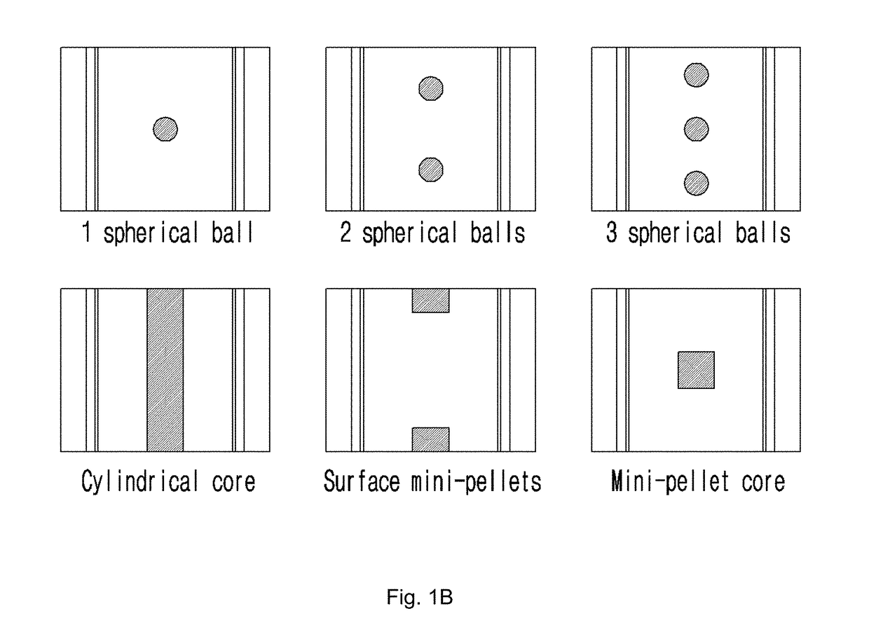
[0076]The effect of CSBA on the commercial core was tested through computerized calculation. For the test, a nuclear fuel assembly model used in Westinghouse AP1000 core was considered. CSBA presented in FIG. 1 B was compared with IFBA generally used for AP1000 model. The results are shown in FIG. 2.

[0077]As shown in FIG. 2, better excess reactivity control than IFBA was possible through the optimization of CSBA, and CSBA could be optimized for core design.

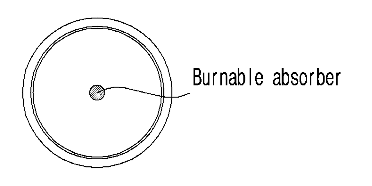
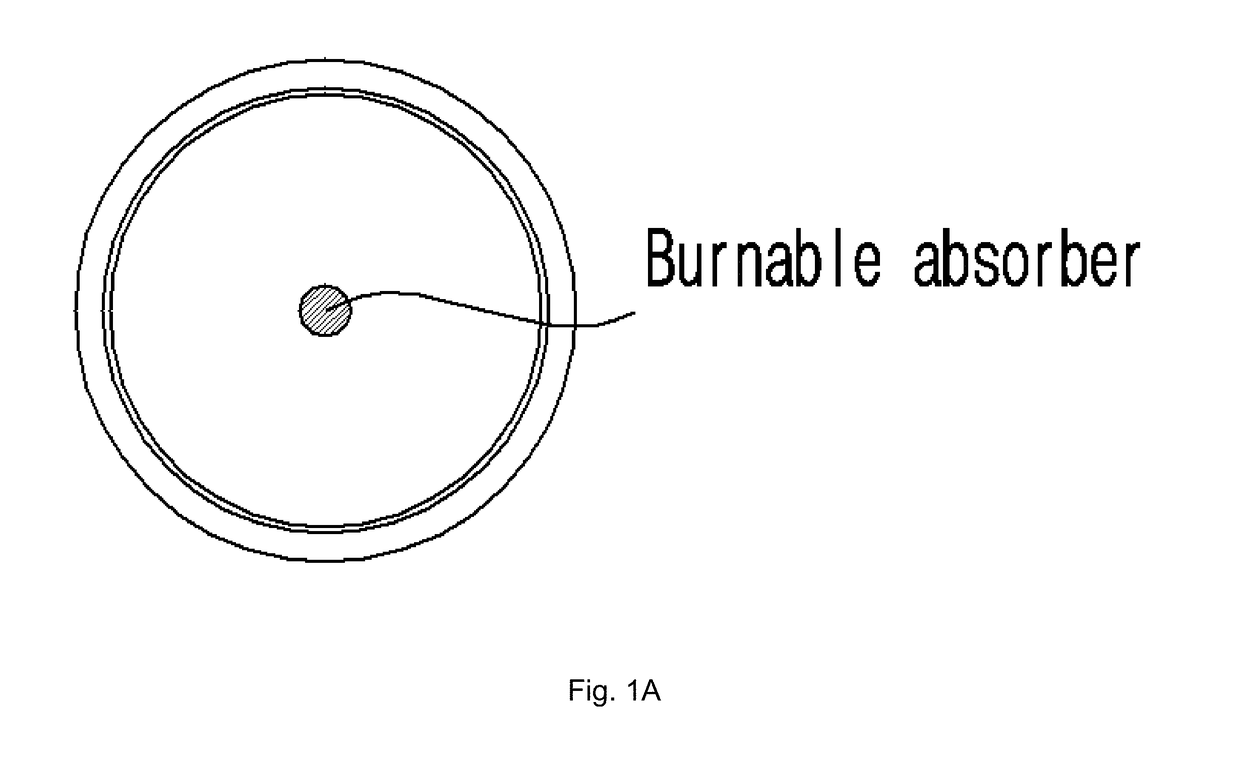
[0078]The present invention provides a sintered nuclear fuel pellet that can regulate the excess reactivity in nuclear fuel efficiently by regulating the shape, the size, and the insertion location of the consolidated body of the burnable absorber.

[0079]According to a preferred embodiment of the present invention, the sintered nuclear fuel pellet can include the consolidated body of the burnable absorber inserted therein. The consolidated body of the burnable absorber is prepared by bulk-processing of the burnable absorber; displa...

example 2

(1) Preparation of Consolidated Body

[0116]The mixed powders of ZrO2-8 mol. % Y2O3(Sigma Aldrich. 99.9%, 8YSZ) and Gd2O3(Sigma Aldrich. 99.9%, 2O3, Gd2O3-5 wt % 8YSZ, Gd2O3-10 wt % 8YSZ, Gd2O3-20 wt % 8YSZ, Gd2O3-30 wt % 8YSZ, and Gd2O3-40 wt % 8YSZ pellets were obtained.

(2) Preparation of Sintered Body

[0117]The obtained pellets were sintered in a microwave sintering apparatus at 1400□, 1500□, and 1600□ for 20 minutes each. As a result, Gd2O3-5 wt % 8YSZ, Gd2O3-10 wt % 8YSZ, Gd2O3-20 wt % 8YSZ, Gd2O3-30 wt % 8YSZ, and Gd2O3-40 wt % 8YSZ sintered bodies were obtained. The XRD patterns of those sintered bodies were measured and shown in FIG. 8.

[0118]As shown in FIG. 8, when yttria-stabilized zirconia was added to gadolinia at the concentration of 5 wt %˜40 wt %, gadolinia was stabilized in a cubic phase from the concentration of 10 wt %. Since the phase change does not occur on the cubic phase to the monoclinic phase during sintering, the soundness of the sintered body can be improved

example 3

[0119]Gd2O3(Sigma Aldrich. 99.9%, 2O3 particles was hundreds □m˜several mm. The mixed powders of the assembled Gd2O3 particles and ZrO2-8 mol. % Y2O3(Sigma Aldrich. 99.9%, 8YSZ) were pressurized at 33.5 MPa, and then CIP was performed at 400 MPa. As a result, Gd2O3, 30 wt % Gd2O3-70 wt % 8YSZ, and 50 wt % Gd2O3-50 wt % 8YSZ pellets were obtained.

[0120]The pellets and ZrO2-8 mol. % Y2O3(Sigma Aldrich. 99.9%, 8YSZ) were placed in a mold, pressurized at 33.5 MPa, and then CIP was performed at 400 MPa. As a result, the nuclear fuel-consolidated body composite with the Gd2O3, 30 wt % Gd2O3-70 wt % 8YSZ, and 50 wt % Gd2O3-50 wt % 8YSZ pellets inserted into the core was prepared. The nuclear fuel-consolidated body composite was sintered in a microwave sintering apparatus at 1600□ for 20 minutes to prepare the sintered nuclear fuel pellet. The SEM images of the prepared sintered body are shown in FIG. 9.

[0121]As shown in FIG. 9, it was confirmed that the sintered nuclear fuel pellet with th...


PUM

PropertyMeasurementUnit
volume fractionaaaaaaaaaa
pressureaaaaaaaaaa

Abstract

The present invention relates to a sintered nuclear fuel pellet comprising a burnable absorber, more precisely a sintered nuclear fuel pellet wherein a burnable absorber is inserted. The present invention can optimize the regulation of excess reactivity [hojin1] by optimizing the self-shielding and the burning speed of the burnable absorber using a consolidated body of the burnable absorber.

Description

BACKGROUND OF THE INVENTION1. Field of the Invention[0001]The present invention relates to a sintered nuclear fuel pellet including a burnable absorber capable of controlling self-shielding and a manufacturing method thereof.2. Description of the Related Art[0002]A nuclear reactor is a reactor that uses the nuclear fission of nuclear fuel to get energy. In the nuclear reactor, energy is generated by the chain reaction of a series of nuclear fissions induced by the neutrons emitted during the nuclear fission. At this time, it is necessary to control properly the reactor core reactivity and the nuclear reactor power distribution in order to operate the nuclear reactor safely and economically.[0003]In a general nuclear reactor, the reactivity is controlled by inserting or withdrawing a control rod made of a neutron absorbing material mechanically. Control of the reactor core reactivity by using such a control rod has the advantage of quick control of the reactor core reactivity. Howeve...

Claims


Application Information

Patent Timeline
Patent Type & Authority Applications(United States)
IPC IPC(8): G21C3/20G21C21/02G21C7/04
CPCG21C3/20G21C21/02G21C7/04G21C2003/045G21Y2002/201G21Y2004/30G21C3/58G21C3/045Y02E30/30
Inventor YONGHEE, KIMRYU, HO JINYAHYA, MOHD SYUKRI BINMISTARIHI, QUSAI MAHMOUD MOHAMMADKIM, CHIHYUNG
Owner KOREA ADVANCED INST OF SCI & TECH
Why Eureka
Try Eureka