
Nuclear fuel rod including disk-type burnable absorber

a technology of nuclear fuel rod and absorber, which is applied in the direction of nuclear elements, greenhouse gas reduction, reactor fuel susbtance, etc., to achieve the effect of improving safety and economy, simple and more economical burnable absorbers, and sufficient verification of performan

Active Publication Date: 2021-04-29
KOREA ADVANCED INST OF SCI & TECH
View PDF0 Cites 0 Cited by
  • Summary
  • Abstract
  • Description
  • Claims
  • Application Information

AI Technical Summary

Benefits of technology

The patent text describes a new method for using a burnable absorber to adjust the excess reactivity of nuclear reactors and improve safety and economy. The method can be applied to future-type LWRs and SMRs and minimize the disadvantages of existing burnable absorbers. The technical effect is the development of a new burnable absorber that can meet the requirements of future-type nuclear reactors and improve safety and economic feasibility.

Problems solved by technology

However, in order to build a very-low-boron or a soluble-boron-free operation environment capable of remarkably improving the inherent safety and economy of the present commercial nuclear reactors and to satisfy the requirements for future-type long-fuel-cycle PWRs and small and medium sized or modular reactors (SMRs), various existing burnable absorbers exhibit obvious limitations thereof, and thus, new-concept burnable absorbers are demanded so as to match the required characteristics.

Method used


Image

  • Nuclear fuel rod including disk-type burnable absorber
  • Nuclear fuel rod including disk-type burnable absorber
  • Nuclear fuel rod including disk-type burnable absorber

Examples


experimental example 1

[0055]As illustrated in FIG. 4, as the nuclear fuel rod of example 1 (DiBA), a nuclear fuel rod was designed in which a unit body was formed such that a burnable absorber was positioned on upper and lower portions of the fuel pellets between the fuel pellets. Here, a was approximately 0.22527 cm, b was approximately 0.12048 cm, c was approximately 0.14048 cm, d was approximately 0.01 cm, e was 0.005 cm, and f was approximately 0.40958 cm. Gd2O3 was applied as burnable absorber materials.

[0056]In addition, CSBAs of related arts were designed as the nuclear fuel rod of comparative example 1 (3-ball CSBA) and the nuclear fuel rod of comparative example 2 (2-ball CSBA). Gadolinium was applied as burnable absorber materials.

[0057]Furthermore, a nuclear fuel was designed in which uranium oxides have approximately 7 wt % of enrichment as a control group (No BA (7 wt % UO2)).

[0058]This experiment was performed by using a computation code Serpent 2, which is capable of very accurate computat...

experimental example 2

[0062]As illustrated in FIG. 6, as the nuclear fuel rod of example 2 (DiBA), a nuclear fuel rod was designed in which a unit body was formed such that a burnable absorber was positioned on upper and lower portions of the fuel pellets between the fuel pellets. And the fuel pellet comprises dishes on upper and lower portions thereof. Here, a was approximately 0.12048 cm, b was approximately 0.22527 cm, c was approximately 0.14048 cm, d was approximately 0.01 cm, e was approximately 0.005 cm, and f was approximately 40,958 cm, the diameter of the groove was approximately 0.40100 cm, and the height of the groove was approximately 0.02500 cm. Gadolinium (Gd) was applied as burnable absorber materials.

[0063]In order to prevent a phenomenon in which the nuclear fuel was irradiated with neutrons and is unevenly expanded, small dishes were formed in upper and lower portions of initial fuel pellets in the manufacturing process. In aspect of reactivity control, since very small amount of nucle...


PUM


Abstract

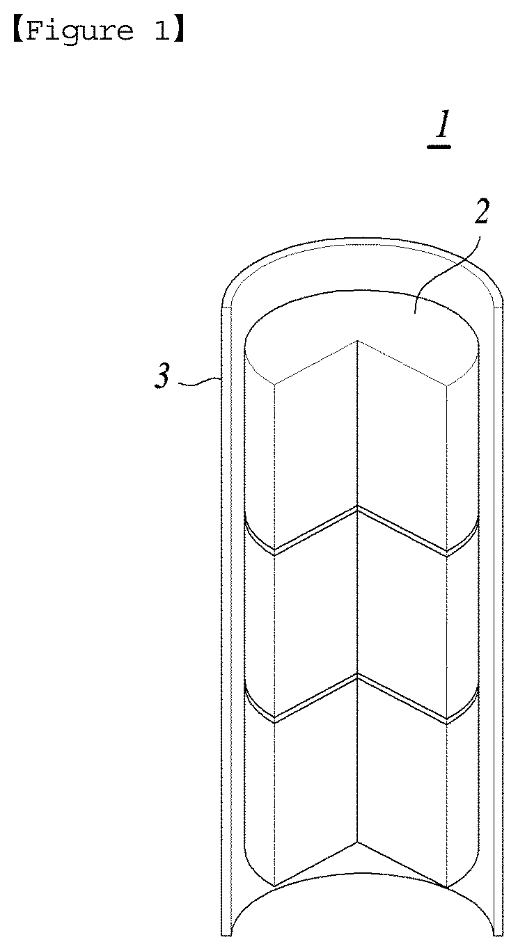
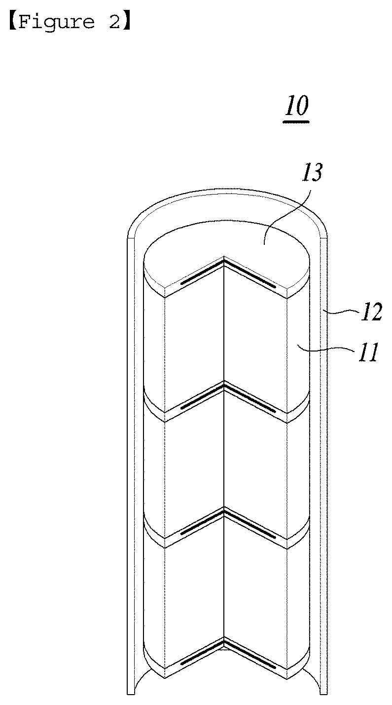
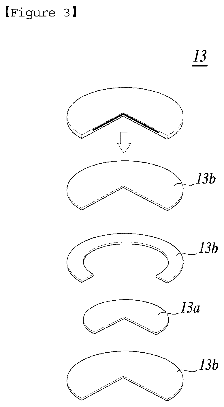
Disclosed is a nuclear fuel rod including at least one or more fuel pellets, a cladding tube surrounding the fuel pellets, and burnable absorber inside the cladding tube. The burnable absorber comprises a burnable absorber material and a cladding material surrounding the burnable absorber material. The burnable absorber has a disk shape, and the cladding material is an alloy comprising zirconium.

Description

CROSS-REFERENCES TO RELATED APPLICATION[0001]This patent application claims the benefit of priority under 35 U.S.C. § 119 from Korean Patent Application No. 10-2019-0135740 filed on Oct. 29, 2019, the contents of which are incorporated herein by reference.BACKGROUND OF THE INVENTION1. Field of the Invention[0002]The present invention relates to a nuclear fuel rod including a burnable absorber.2. Description of the Related Art[0003]Nuclear power plants refer to power plants in which electricity is produced from nuclear energy released from a nuclear reaction. Commercial nuclear power plants based on a nuclear fission chain reaction are classified, according to methods for slowing down neutrons and the neutron energy thereby, into pressurized water reactors (PWRs), pressurized heavy water reactors (PHWRs), boiling water reactors (BWRs), and fast reactors (FRs). The basic principle of a nuclear fission chain reaction is repetitive process that a fissile material such as uranium 235 (U-...

Claims


Application Information

Patent Timeline
Patent Type & Authority Applications(United States)
IPC IPC(8): G21C7/04G21C3/04G21C21/02
CPCG21C7/04G21C21/02G21C3/045G21C3/06G21C3/16G21C3/18Y02E30/30G21C7/06G21C3/07G21C3/62Y10S376/901
Inventor KIM, YONGHEEJANG, SEONGDONGNGUYEN, XUAN HA
Owner KOREA ADVANCED INST OF SCI & TECH
Learn More