Wire bonding apparatus

a technology of wire bonding and wire, which is applied in the direction of non-electric welding apparatus, welding apparatus, manufacturing tools, etc., can solve the problems of long short service life of wire, and inability to protrude from wire for forming a tail, etc., and achieves the effect of convenient protruding, smooth protruding, and extended usage period of capillary

Inactive Publication Date: 2018-05-31
KAIJOO KK
View PDF16 Cites 5 Cited by
  • Summary
  • Abstract
  • Description
  • Claims
  • Application Information

AI Technical Summary

Benefits of technology

[0034]In the wire bonding apparatus according to the one embodiment of the present invention, after the wire is inserted through the capillary and the wire is cut at the leading end of the capillary, the wire can be automatically protruded from the leading end of the capillary. Therefore, the wire can be easily protruded without forming an unnecessary dent on the bonding workpiece. Further, the wire bonding apparatus can be operated with a minimum wire consumption amount.
[0035]Further, in the wire bonding apparatus, deposited matters adhere to the leading end of the capillary during the bonding, and thus the protrusion of the wire is inhibited. Therefore, cleaning of the capillary is required. The wire bonding apparatus according to the one embodiment of the present invention cleans the capillary by vertically moving the leading end of the capillary at high speed so that the leading end repeatedly abuts against the surface of the cleaning sheet having an adhesive property. In this manner, the deposited matters on the leading end of the capillary and the dirt adhering to the inside of the capillary can be peeled off. Therefore, after the capillary is cleaned, the wire can be smoothly protruded.
[0036]Further, cleaning the leading end of the capillary enables the usage period of the capillary to be extended. Further, the number of times of replacement of the capillary can be reduced, and hence the time required for the replacement of the capillary can be reduced. Thus, the operating rate of the wire bonding apparatus can be improved, and the cost of the bonding components can be reduced.
[0037]Further, in the present invention, the capillary cleaning and the protrusion (wire tail formation) operation of the wire at the leading end of the capillary are automatically performed, and thus the wire bonding apparatus can be operated without a stop. Therefore, the continuous operating time may be significantly improved.

Problems solved by technology

In a wire bonding apparatus configured to bond a pad of an IC chip, which serves as the first bonding point, and as the second bonding point, for example, a lead of a lead frame made of a metal to each other with use of a wire, the bonding property between the surface of the lead and the wire at the second bonding point may be insufficient in some cases, and thus bonding failure or fall-out of the wire may be caused.
However, in Japanese Patent No. 4467631 and Japanese Patent Application Laid-open No. 2010-161377, depending on the bonding state at the second bonding point, for example, the cut wire may adhere to the inside of the leading end of the capillary or the wire may strongly bite into the edge inside the capillary, and thus a wire for forming a tail may fail to be protruded (fed out).
Further, the capillary is raised in order to form a tail of the wire, but when the wire located below the second clamper is buckled, the wire may fail to be protruded.
Meanwhile, as disclosed in Japanese Patent Application Laid-open No. 2011-66278, the wire is fed out of the capillary by simply raising the capillary while applying ultrasonic vibration to the capillary, but the distance between the capillary and the second clamper is long, and hence the wire is easily buckled.
Thus, the wire may fail to be protruded from the capillary.
Therefore, it may be difficult to pull out the wire from the capillary only by the wind pressure of the air.
Further, the wire protrusion operation with use of air requires time for starting the operation because the response time of the air tension is decreased due to pipes for the air or other factors.
Therefore, the wire bonder may fail to perform high-speed operation.
However, when the wire adheres to the inside of the leading end of the capillary, the ultrasonic vibration or the reciprocating operation in the XY directions cannot apply a force necessary for separating the wire from the capillary, and hence the wire may fail to be protruded from the capillary.
Further, regarding the capillary cleaning disclosed in Japanese Patent Application Laid-open No. 2011-66278 and Korean Patent No. 10-1312148, when the capillary is cleaned only by the ultrasonic vibration, the vibration width of the capillary is small, and hence a force for peeling off deposited matters on the leading end of the capillary may not be sufficiently obtained.
Thus, a sufficient cleaning effect may not be obtained.

Method used


Image

  • Wire bonding apparatus
  • Wire bonding apparatus
  • Wire bonding apparatus

Examples


Embodiment Construction

[0049]Now, with reference to the drawings, a wire bonding apparatus according to an embodiment of the present invention is described. According to the present invention, a wire can be automatically protruded from a leading end of a capillary without being affected by a bonding state at a second bonding point or members such as the capillary and the wire. Further, cleaning of removing dirt on the capillary during bonding and protrusion of the wire after the capillary is cleaned can be reliably performed. Thus, an operating rate of the wire bonding apparatus is significantly improved.

[0050][Configuration of Wire Bonding Apparatus]

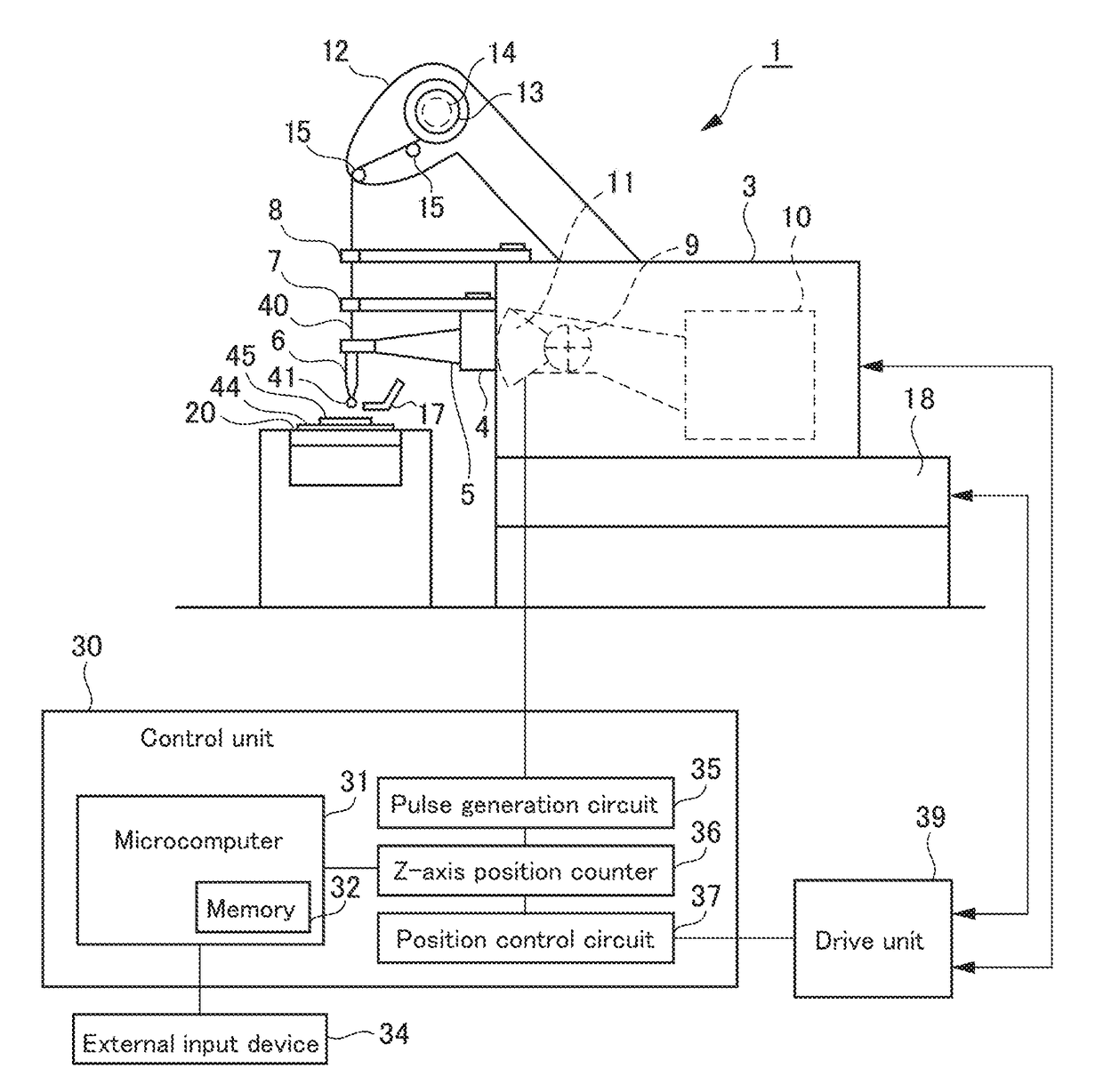
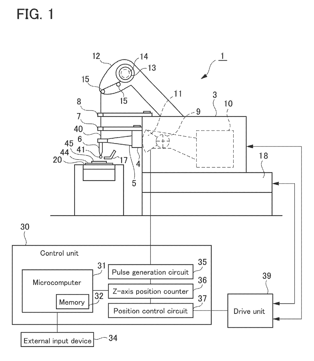
[0051]FIG. 1 is a diagram for illustrating a configuration of the wire bonding apparatus of the present invention. As illustrated in FIG. 1, a wire bonding apparatus 1 includes a bonding head 3, an XY stage 18 serving as positioning means, on which the bonding head 3 is mounted, for positioning the bonding head 3 by two-dimensionally moving the bonding head 3...


PUM

PropertyMeasurementUnit
frequencyaaaaaaaaaa
distanceaaaaaaaaaa
ultrasonic vibrationaaaaaaaaaa

Abstract

To provide a wire bonding apparatus, which is insusceptible to a bonding state at a second bonding point due to a wire cut error or the like, or to members such as a capillary and a wire, and is capable of automatically protruding the wire from a leading end of the capillary, provided is a wire bonding apparatus including: a capillary (6) having a through hole through which a wire (40) is to be inserted; a holding unit, which is provided above the capillary (6), and is configured to hold the wire (40) inserted through the capillary (6); and a vibrating unit configured to vertically vibrate the capillary (6). Under a state in which the holding unit holds the wire (40), the vibrating unit vertically vibrates the capillary (6) so that the wire (40) is protruded from the leading end of the capillary.

Description

BACKGROUND OF THE INVENTION1. Field of the Invention[0001]The present invention relates to a wire bonding apparatus configured to connect an electrode of a component to be bonded and a lead to each other with use of a wire, and more particularly, to a wire bonding apparatus capable of automatically protruding a wire from a leading end of a capillary.2. Description of the Related Art[0002]Hitherto, there has been used a wire bonding apparatus configured to connect an electrode (pad) on an IC chip, which serves as a first bonding point, and a lead, which serves as a second bonding point, to each other with use of a wire made of gold, copper, or other materials.[0003]In a wire bonding apparatus configured to bond a pad of an IC chip, which serves as the first bonding point, and as the second bonding point, for example, a lead of a lead frame made of a metal to each other with use of a wire, the bonding property between the surface of the lead and the wire at the second bonding point ma...

Claims


Application Information

Patent Timeline
Patent Type & Authority Applications(United States)
IPC IPC(8): H01L23/00B23K1/06B23K1/00B23K3/06B23K3/08
CPCH01L24/78B23K1/06B23K1/0016B23K3/063B23K3/08H01L2224/78301H01L2224/78621H01L2224/78353H01L2224/78925H01L2224/7801B23K2201/36H01L2224/78H01L24/45H01L2224/45144H01L2224/45147H01L2224/85045H01L2224/85205H01L2224/78268H01L24/85H01L2224/789H01L2224/78901H01L2224/859H01L2924/14B23K20/007B23K2101/42H01L2924/00014H01L24/745B23K2101/36
Inventor JINDO, RIKISUGITO, AKIO
Owner KAIJOO KK
Why Eureka
Try Eureka