
Wire connection structure and harness manufacturing method

a manufacturing method and wire connection technology, applied in the direction of connection contact material, connection effected by permanent deformation, line/current collector details, etc., can solve the problems of easy pulling apart of the conductor of the stranded wire, stranded protruding, and difficult welding of ultrasonic welding, so as to reduce contact resistance, reduce the effect of compression ratio, and increase the thickness

Inactive Publication Date: 2020-06-18
AUTONETWORKS TECH LTD +2
View PDF0 Cites 1 Cited by
  • Summary
  • Abstract
  • Description
  • Claims
  • Application Information

AI Technical Summary

Benefits of technology

The patent text describes a wire fixing portion that has a thick portion along the circumferential direction of the core and is compressed at a higher ratio than the other parts. This high compression ratio breaks an oxide film on the surface of the core to expose a new surface of metal, reducing contact resistance between the core, the connecting conductor, and the crimping terminal. The core is also compressed with a lower force to prevent breakage. The wire fixing portion is positioned between the core and the wire barrels to prevent the core from protruding during the crimping step. The technical effect of this configuration is to improve the electrical performance of the wire and to protect the core from damage during crimping.

Problems solved by technology

However, joining by ultrasonic welding is problematic in that the conductor of the stranded wire easily is pulled apart from the conductor of the round bar wire if the stranded wire is pulled upward.
On the other hand, crimping barrels to wrap around the conductor of the stranded wire can cause the strands to protrude and a short circuit may occur between circuits due to contact of the protruding strands with another circuit.

Method used


Image

  • Wire connection structure and harness manufacturing method
  • Wire connection structure and harness manufacturing method
  • Wire connection structure and harness manufacturing method

Examples


Embodiment Construction

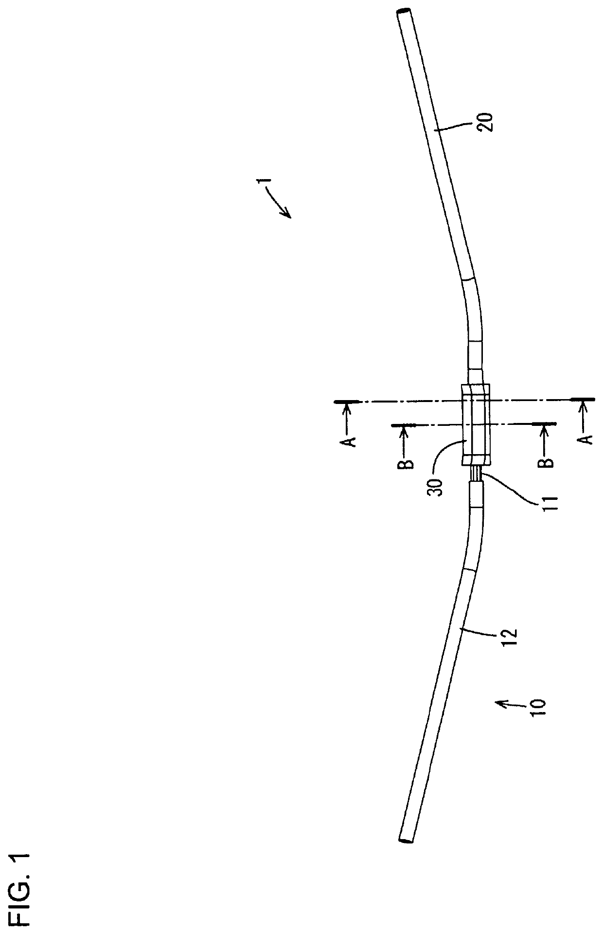
[0023]An embodiment is described with reference to FIGS. 1 to 12. A wire connection structure of this embodiment is a part of a harness 1 in which a wire 10 and a single-core wire 20 (corresponding to a connecting conductor) are connected using a splice terminal 30 (corresponding to a crimping terminal), as shown in FIG. 1.

[0024]The wire 10 is an aluminum wire of a known configuration including a core 11 and an insulation coating 12. The core 11 is a stranded wire formed by twisting a plurality of strands made of aluminum or aluminum alloy. The insulation coating 12 is made of synthetic resin and coats the core 11. As shown in FIG. 1, the insulation coating 12 is stripped to expose the core 11 at an end part of the wire 10.

[0025]The single-core wire 20 is made of copper or copper alloy and includes, as shown in FIG. 5, a body 21 in the form of a solid round bar and a wire fixing portion 23 connected to one end of the body 21 via a coupling 22. The coupling 22 extends along an axial ...


PUM


Abstract

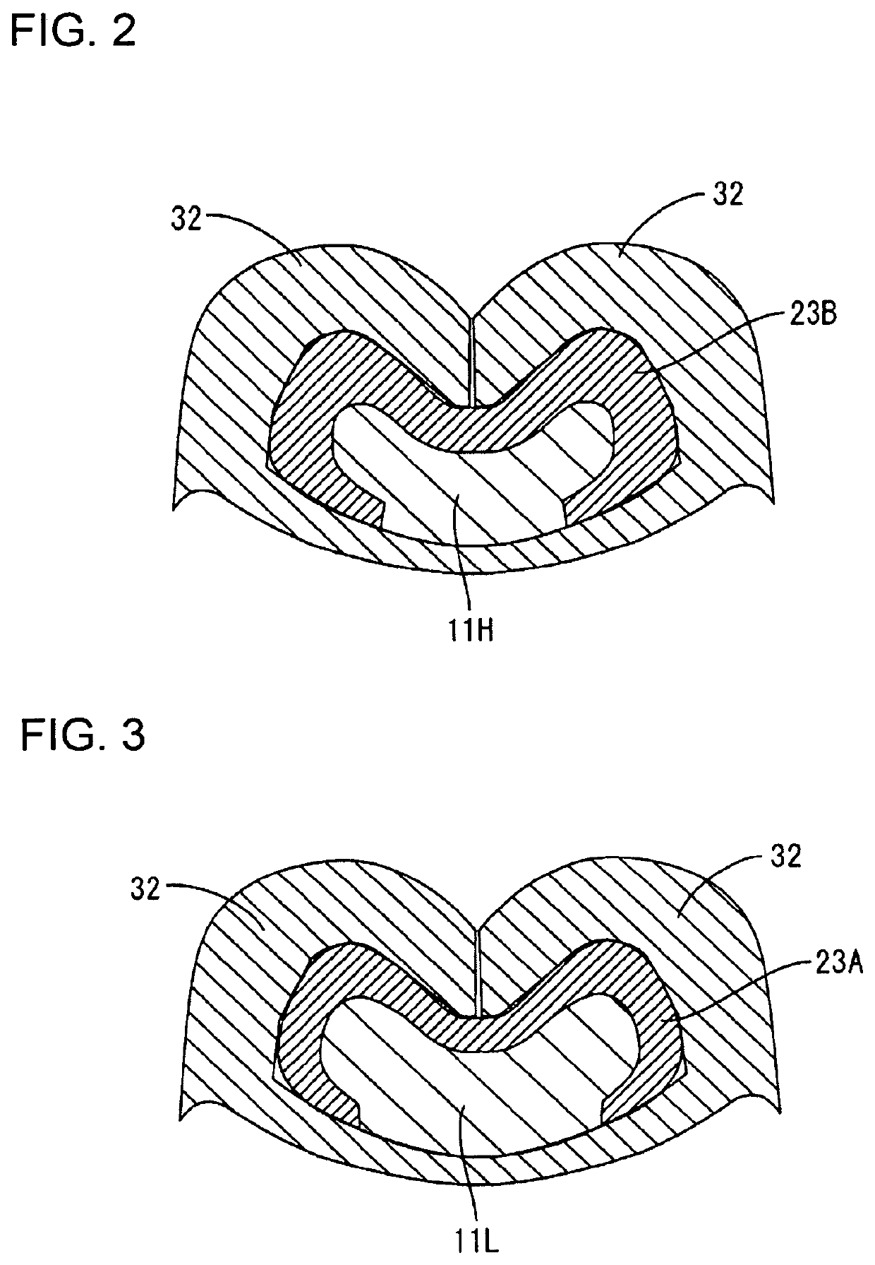
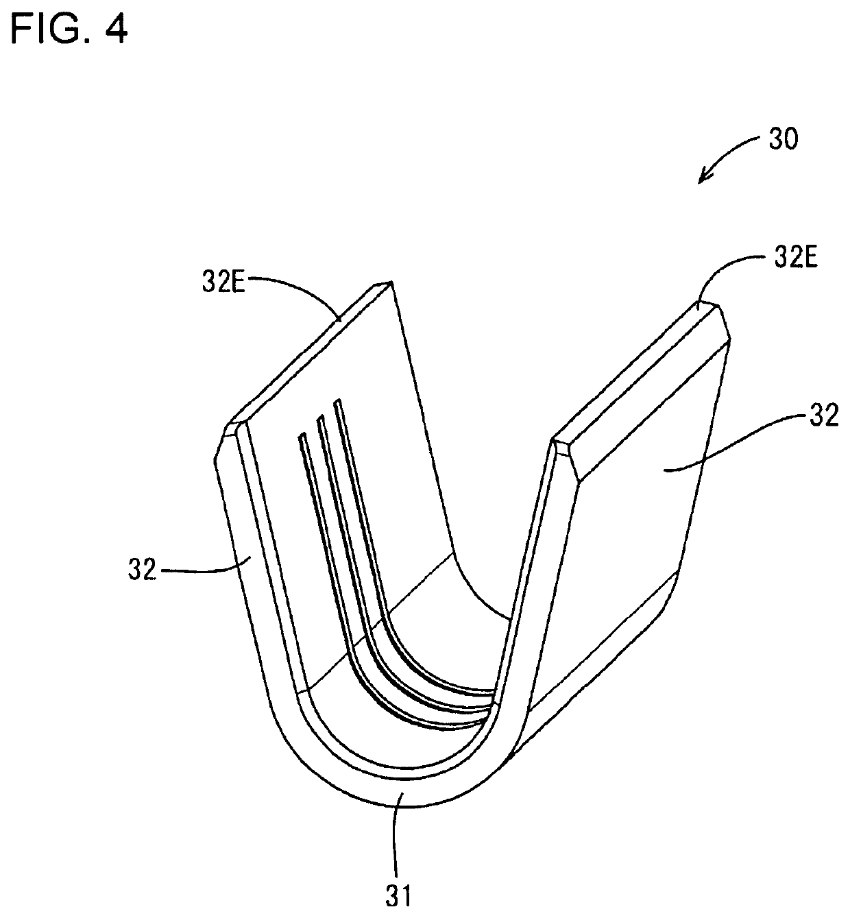
A harness 1 is provided with a wire 10 including a core 11 constituted by a plurality of strands and an insulation coating 12 coating the core 11, a single-core wire 20 including a body portion 21 and a wire fixing portion 23 extending from the body portion 21 and arranged to cover the core 11, and a splice terminal 30 including a bottom plate portion 31, the core 11 being arranged on the bottom plate portion 31, and a pair of wire barrel portions 32 extending from the bottom plate portion 31 and wound from outside the wire fixing portion 23. According to this configuration, since the wire fixing portion 23 of the single-core wire 20 is interposed between the core 11 and the wire barrel portions 32, it can be avoided that the core 11 protrudes from butting parts of the pair of wire barrel portions 32.

Description

BACKGROUNDField of the Invention[0001]This specification relates to a wire connection structure and a harness manufacturing method.Related Art[0002]Japanese Unexamined Patent Publication No. 2013-25997 discloses a wire connection structure in which a round bar wire and a stranded wire are connected. The round bar wire includes a conductor formed into a flat plate body. On the other hand, the stranded wire includes a conductor formed by twisting a plurality of strands. A connection is formed by overlapping the conductor of the stranded wire on the conductor of the round bar wire and performing ultrasonic welding.[0003]However, joining by ultrasonic welding is problematic in that the conductor of the stranded wire easily is pulled apart from the conductor of the round bar wire if the stranded wire is pulled upward. On the other hand, crimping barrels to wrap around the conductor of the stranded wire can cause the strands to protrude and a short circuit may occur between circuits due t...

Claims


Application Information

Patent Timeline
Patent Type & Authority Applications(United States)
IPC IPC(8): H01R4/18H01R43/048
CPCH01R43/048H01R4/184H01R4/60
Inventor WASHIO, KAZUHIROMIYAMOTO, KENJIKAWATA, YUJI
Owner AUTONETWORKS TECH LTD
Learn More