Aircraft fire seal structure and aircraft

a technology for aircraft and fire seals, applied in the direction of ducting arrangements, heating types, lighting and heating apparatuses, etc., can solve the problems of increased weight of fire seals, inferior fire resistance of elastic seals containing silicone rubber to metal materials such as stainless steel, etc., to reduce maintenance burden and improve fire seal performance

Active Publication Date: 2018-06-07
MITSUBISHI AIRCRAFT
View PDF11 Cites 7 Cited by
  • Summary
  • Abstract
  • Description
  • Claims
  • Application Information

AI Technical Summary

Benefits of technology

[0007]One or more embodiments of the present invention provide a fire seal structure for an aircraft that makes it possible to improve fire seal performance without necessity of adding a flame-shielding member and to reduce burden of maintenance, and to provide an aircraft.

Problems solved by technology

The elastic seal containing a rubber material such as silicone rubber is inferior in fire resistance to a metal material such as stainless steel.
If a member that shields the elastic seal from flame is necessary in order to delay a time until the fire seal performance is lost due to deterioration of adhesion between the elastic seal and a partner member through exposure to flame and burning down of the elastic seal, the weight of the fire seal structure is increased.

Method used


Image

  • Aircraft fire seal structure and aircraft
  • Aircraft fire seal structure and aircraft
  • Aircraft fire seal structure and aircraft

Examples


Embodiment Construction

[0035]Embodiments of the present invention are described below with reference to the accompanying drawings.

[0036]In the embodiments described below, a fire seal structure that prevents flame from coming out of a fire-prevention region is described. The fire-prevention region is defined on the assumption of auxiliary power unit (APU) as an ignition source.

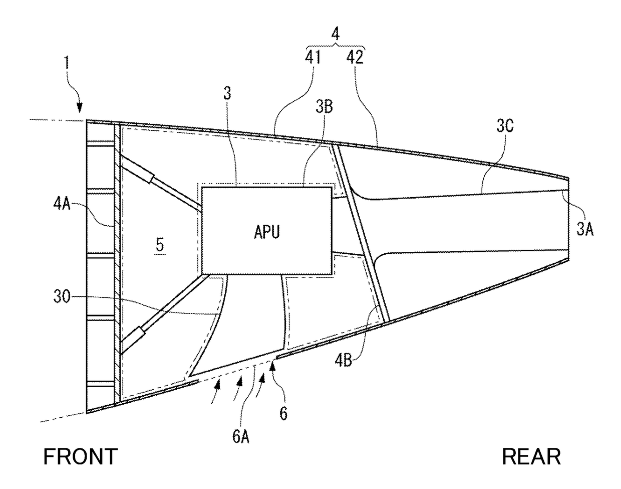
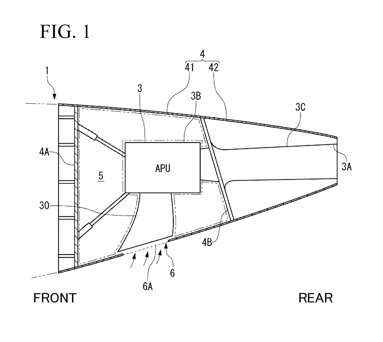
[0037]An auxiliary power unit 3 (hereinafter, referred to as APU) is provided at a rear end portion of an aircraft 1 illustrated in FIG. 1 according to one or more embodiments of the invention.

[0038]A tail cone 4 that is continuous to a rear end of a fuselage of the aircraft 1 is gradually decreased in diameter toward a terminal end at which an exhaust port 3A of the APU 3 is located. The tail cone 4 houses a main body 3B of the APU 3, an exhaust nozzle 3C, an intake duct 30, and accessories, meters, piping, etc. of the APU 3. An inside of the tail cone 4 and an inside of the fuselage provided forward thereof are partitioned by a bu...


PUM


Abstract

A fire seal structure prevents flame from coming out of a fire-prevention region of an aircraft including a panel and a duct. The fire seal structure includes: a first member provided on the duct at a connection portion between the panel and the duct; and a second member that faces the first member around the opening and is provided on the panel. The panel defines the fire-prevention region. The duct communicates with an opening provided in the panel. The duct defines, together with the panel, the fire-prevention region. The first and the second members each contain refractory material, and the first and the second members form a labyrinth-shaped gap between the duct and the panel.

Description

BACKGROUND OF THE INVENTIONField of the Invention[0001]The present invention relates to a fire seal structure that prevents flame from coming out of a fire-prevention region of an aircraft.Description of the Related Art[0002]A fire-prevention region is designated around an ignition source from which flame may originate, such as an engine main body and an auxiliary power unit of an aircraft, and it is required to prevent the flame originating inside the fire-prevention region from coming out of the fire-prevention region.[0003]For example, the fire-prevention region that confines the flame originating from the engine main body (engine core) is designated inside an engine nacelle.[0004]When the fire originates from the engine main body, it is necessary to prevent the flame from coming through a gap between the engine nacelle and a pylon to blow off to outside. Accordingly, the gap between the engine nacelle and the pylon is sealed by an elastic seal (JP 2014-141202 A).[0005]The elasti...

Claims


Application Information

Patent Timeline
Patent Type & Authority Applications(United States)
IPC IPC(8): F16J15/06B64D41/00B64D45/00F24F13/02
CPCF16J15/065B64D41/00B64D45/00F24F13/0209B64D2033/0213B64D2045/009B64C1/1446Y02T50/40
Inventor TAKEUCHI, AKIRA
Owner MITSUBISHI AIRCRAFT
Why Eureka
Try Eureka