
Optical micromesh for computerized devices

a computerized device and optical micro-meshing technology, applied in the field of optical micro-mesh for computerized devices, can solve problems such as reducing the depth mapping performance, and achieve the effect of avoiding collisions between talk and communication, and avoiding collisions of multiple simultaneous laser emissions

Active Publication Date: 2018-06-07
SONY CORP +1
View PDF16 Cites 0 Cited by
  • Summary
  • Abstract
  • Description
  • Claims
  • Application Information

AI Technical Summary

Benefits of technology

This patent describes a system that uses multiple cameras and lasers to create a three-dimensional map of a space. The cameras are synchronized to avoid collisions with the lasers, and the lasers communicate using time-domain multiplexing to prevent cross-talk and collisions. The system allows for dynamic mapping of node locations, which can be useful in various applications such as autonomous vehicles or augmented reality.

Problems solved by technology

In the case that an active illumination system is used and the time of flight method is used, interference can occur which would otherwise reduce the performance of the depth mapping if there are multiple systems which have over lapping areas of illumination.

Method used


Image

  • Optical micromesh for computerized devices
  • Optical micromesh for computerized devices
  • Optical micromesh for computerized devices

Examples


Embodiment Construction

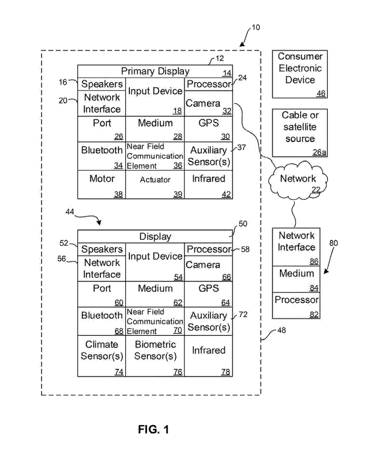
[0022]This disclosure relates generally to computer ecosystems including aspects of multiple computerized devices. A system herein including computerized devices may include server and client components, connected over a network such that data may be exchanged between the client and server components. The client components may include one or more computing devices such as portable televisions (e.g. smart TVs, Internet-enabled TVs), portable computers such as laptops and tablet computers, and other mobile devices including smart phones and additional examples discussed below. These client devices may operate with a variety of operating environments. For example, some of the client computers may employ, as examples, operating systems from Microsoft, or a Unix operating system, or operating systems produced by Apple Computer or Google. These operating environments may be used to execute one or more browsing programs, such as a browser made by Microsoft or Google or Mozilla or other bro...


PUM


Abstract

Multiple camera systems which use laser illumination for ranging benefit from a heartbeat to synchronize the timing of the individual lasers to eliminate collisions of multiple simultaneous laser emissions. An optical micromesh system provides for the dynamic entry and egress of mobile and stationary nodes. The optical communication between nodes may be controlled using time domain multiplexing (TDM) to avoid cross talk and communication collision due to overlapping laser illumination. By using an optical, laser based micromesh network, laser ranging can be used to dynamically map node location.

Description

FIELD[0001]The present application relates to technically inventive, non-routine solutions that are necessarily rooted in computer technology and that produce concrete technical improvements.BACKGROUND[0002]When multiple computerized devices interact with each other at close range, they may employ sensors such as cameras and laser range finders to map their environment. As understood herein, the use of such sensors by multiple devices can cause mutual interference due to overlapping emissions of laser illumination.SUMMARY[0003]As understood herein, multiple camera systems which use laser illumination for ranging benefit from a heartbeat to synchronize the timing of the individual lasers to eliminate collisions of multiple simultaneous laser emissions. An optical micromesh system provides for the dynamic entry and egress of mobile and stationary nodes. The optical communication between nodes may be controlled using time domain multiplexing (TDM) to avoid cross talk and communication ...

Claims


Application Information

Patent Timeline
Patent Type & Authority Applications(United States)
IPC IPC(8): G01S7/491G01S17/08G01S7/497G01S17/89G01S17/87
CPCG01S7/4911G01S17/89G01S7/497G01S17/08H04B10/114G01S17/87G01S7/484
Inventor SHINTANI, PETERGONZALEZ HERNANDEZ, JOSE OMARCLAY, WILLIAMESPINOSA, PABLO ANTONIOANSFIELD, FREDMOHAPATRA, BIBHUDENDURESCH, KEITHUSAMI, MORIO
Owner SONY CORP
Features
  • Generate Ideas
  • Intellectual Property
  • Life Sciences
  • Materials
  • Tech Scout
  • Unparalleled Data Quality
  • Higher Quality Content
  • 60% Fewer Hallucinations
Learn More