
A driving system for a display device, and driving circuit applicable to OLED

a technology of driving system and display device, applied in the field of display technologies, can solve the problems reducing the luminous efficiency of the oled, so as to eliminate the phenomenon of shortening the lifetime of the oled

Inactive Publication Date: 2018-06-07
SHENZHEN CHINA STAR OPTOELECTRONICS TECH CO LTD
View PDF4 Cites 10 Cited by
  • Summary
  • Abstract
  • Description
  • Claims
  • Application Information

AI Technical Summary

Benefits of technology

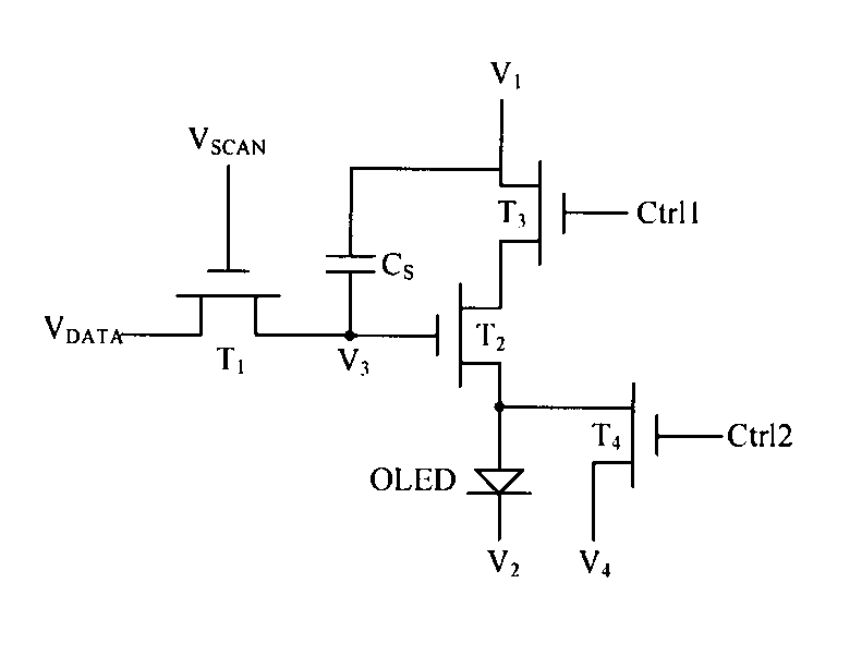
The present invention provides a driving system for a display device that prevents the OLED from getting damaged by a long-term DC bias light-emitting state. This is achieved by using a reverse bias unit to control the reverse bias of the OLED when a black picture is inserted between two frames. This not only eliminates residual electric charge in the OLED but also ensures that the reverse bias does not affect the display effect of the display device.

Problems solved by technology

In the prior art, during a display procedure of an organic light-emitting diode (OLED for short) display device, an electric field of a long-time loaded DC driving voltage causes polarization of OLED internal ions, and formation of a built-in electric field, which increases an OLED threshold voltage, greatly reduces luminous efficiency of the OLED, and shortens lifetime of the OLED.
A long-term DC bias light-emitting state of the OLED accelerates polarization of organic materials, thereby enhancing the built-in electric field of the OLED, increasing the OLED threshold voltage, remarkably reducing the luminous efficiency of the OLED, and shortening the lifetime of the OLED.

Method used


Image

  • A driving system for a display device, and driving circuit applicable to OLED
  • A driving system for a display device, and driving circuit applicable to OLED
  • A driving system for a display device, and driving circuit applicable to OLED

Examples


example 1

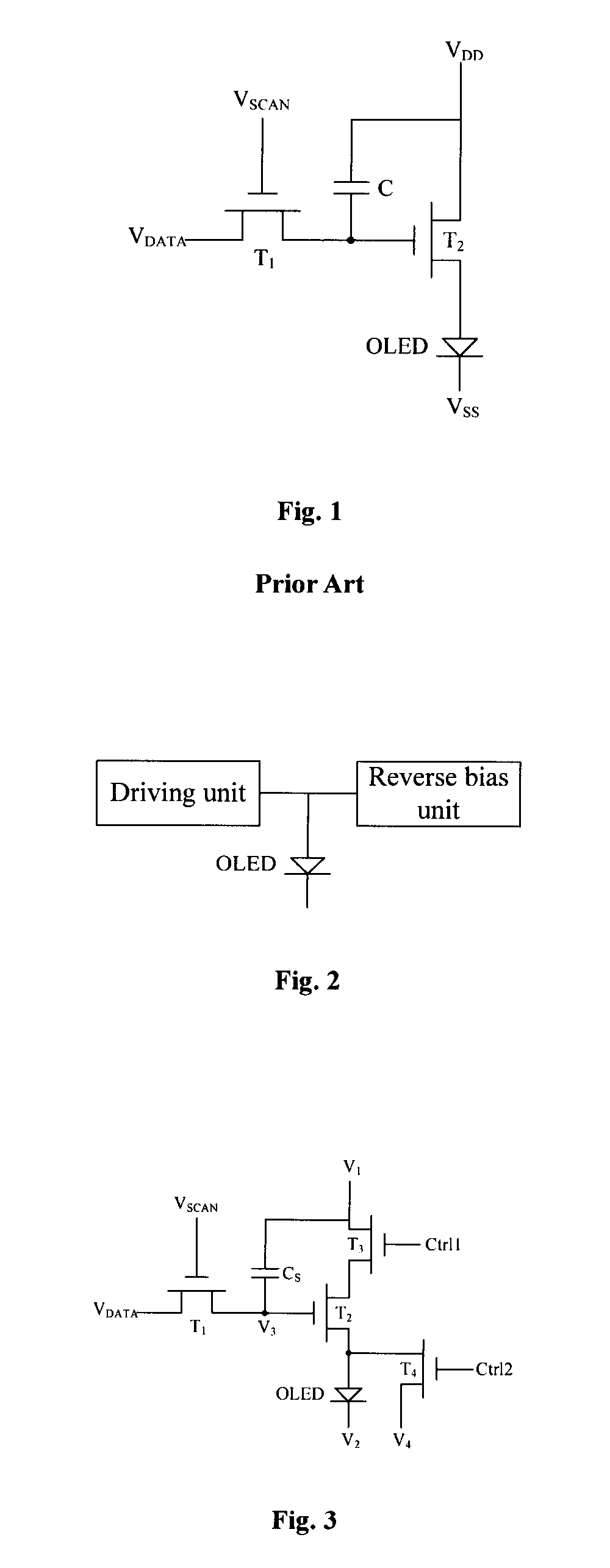
[0033]A driving circuit applicable to an OLED is provided in an embodiment of the present disclosure. As shown in FIG. 2, the driving circuit includes a driving unit connected to a scan line and a data line for driving the OLED, and a reverse bias unit connected to the OLED.

[0034]In the prior art, the OLED is always in a DC bias light-emitting state. That is, a potential of an anode of the OLED is higher than that of a cathode thereof. This easily enhances a built-in electric field of the OLED and increases an OLED threshold voltage, thereby greatly reducing the luminous efficiency and shortening the lifetime of the OLED.

[0035]In order to eliminate the built-in electric field of the OLED, it is necessary to reverse-bias the OLED. However, if the OLED is in a reverse bias state, it will not emit light smoothly. Thus an entire display device will enter a black screen state. Therefore, in the embodiment of the present disclosure, the reverse bias unit controls reverse-bias of the OLED ...

example 2

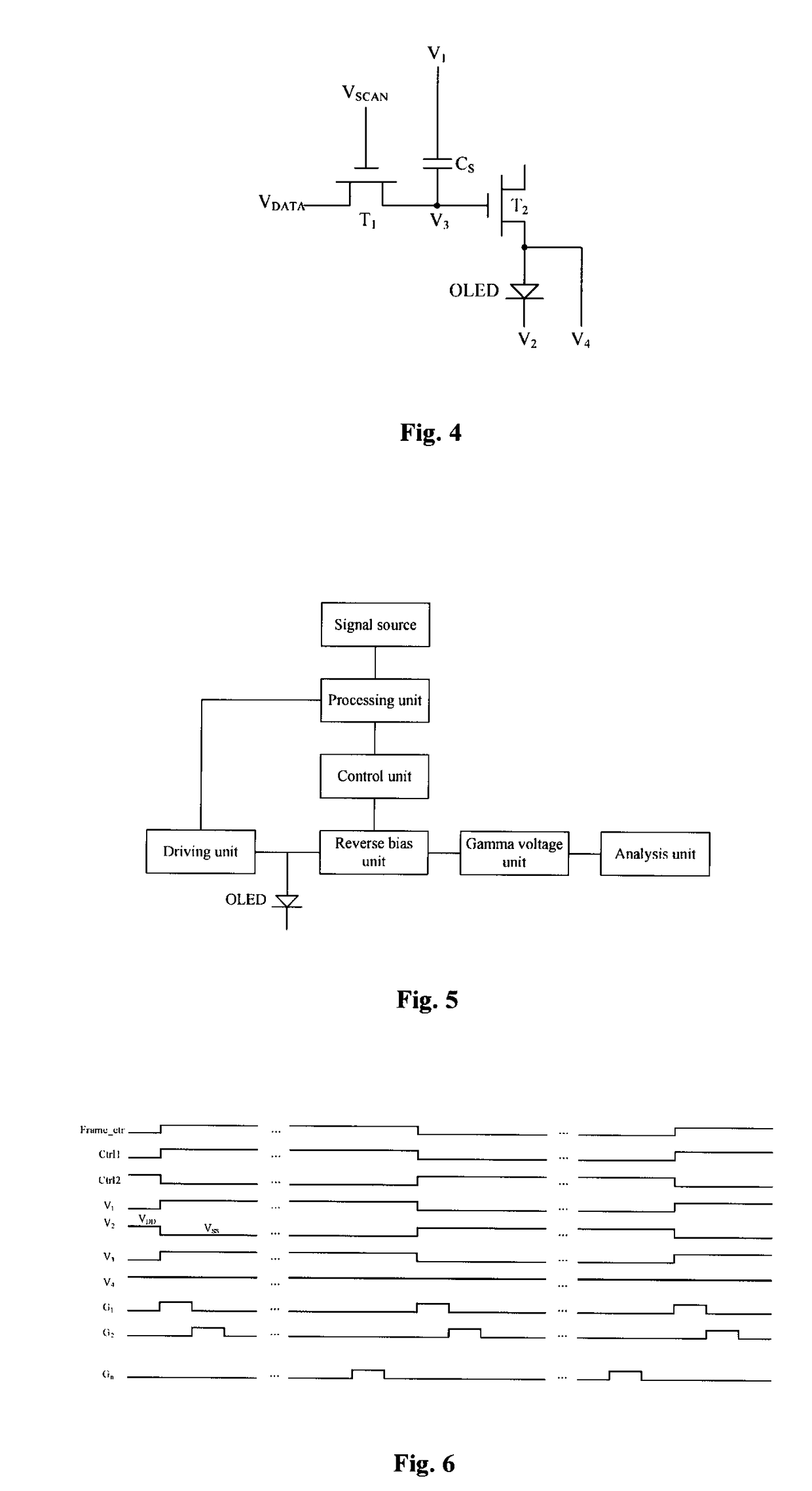
[0044]The present embodiment provides a driving system of a display device, which includes, as shown in FIG. 5, a driving circuit as shown in FIG. 2, and further comprises:

[0045]a processing unit, which buffers a data signal from a signal source, performs frame multiplication on the data signal by insertion of a black picture between adjacent two data signal frames, and outputs frame multiplied data signal to a display panel.

[0046]The principle of frequency multiplication technology is to add a black picture frame between two conventional image frames, so as to increase a refresh rate of an ordinary display device from 60 Hz up to 120 Hz, and increase a display signal thereof from previous 60 frames per second up to now 120 frames per second, thus effectively solving the problems such as image blurring and smearing generated during play of motion pictures by the display device. This is favorable for clearing an image blur from a previous frame to improve a dynamic clarity effect, an...


PUM


Abstract

Provided is a driving system for a display device and a driving circuit applicable to an OLED, which belong to the field of display technology, and can eliminate the phenomenon of shortening in lifetime of the OLED caused by a long-term DC bias light-emitting state of the OLED.

Description

CROSS-REFERENCE TO RELATED APPLICATIONS[0001]The present application claims the priority of Chinese patent application CN 201510583321.3, entitled “A driving system for a display device, and a driving circuit applicable to OLED” and filed on Sep. 15, 2015, the entirety of which is incorporated herein by reference.FIELD OF THE INVENTION[0002]The present disclosure relates to the field of display technologies, and in particular, to a driving system for a display device, and a driving circuit applicable to an OLED.BACKGROUND OF THE INVENTION[0003]In the prior art, during a display procedure of an organic light-emitting diode (OLED for short) display device, an electric field of a long-time loaded DC driving voltage causes polarization of OLED internal ions, and formation of a built-in electric field, which increases an OLED threshold voltage, greatly reduces luminous efficiency of the OLED, and shortens lifetime of the OLED.[0004]As shown in FIG. 1, an existing 2T1C pixel unit driving ...

Claims


Application Information

Patent Timeline
IPC IPC(8): G09G3/3225
CPCG09G3/3225G09G2320/045G09G2320/0673G09G2310/027G09G2320/0233G09G2320/0238G09G3/3233G09G2310/0251G09G2320/0204
Inventor WANG, ZHENLINGHWANG, TAI JIUN
Owner SHENZHEN CHINA STAR OPTOELECTRONICS TECH CO LTD
Learn More