Integrated casting core-shell structure with floating tip plenum

a technology of integrated casting and tip plenum, which is applied in the direction of manufacturing tools, foundry patterns, moulding apparatus, etc., can solve the problems of inconvenient manufacturing of positional precision and intricate internal geometries using these conventional manufacturing processes, and achieve the effect of sufficient strength

Inactive Publication Date: 2018-06-14
GENERAL ELECTRIC CO
View PDF4 Cites 32 Cited by
  • Summary
  • Abstract
  • Description
  • Claims
  • Application Information

AI Technical Summary

Benefits of technology

[0007]In one embodiment, the invention relates to a method for fabricating a ceramic mold including steps (a)-(d). Step (a) involves contacting a cured portion of a workpiece with a liquid ceramic photopolymer. Step (b) involves irradiating a portion of the liquid ceramic photopolymer adjacent to the cured portion through a window contacting the liquid ceramic photopolymer. Step (c) involves removing the workpiece from the uncured liquid ceramic photopolymer; and (d) repeating steps (a)-(c) until a ceramic mold is formed. The ceramic mold formed in the process includes a main core portion, a core tip portion, and a shell portion with at least one cavity between the core portion and the shell portion. The cavity defines the shape of a cast component upon casting and removal of the ceramic mold. At least one ceramic tip filament connects the core tip portion and the shell portion. The t...

Problems solved by technology

Many modern engines and next generation turbine engines require components and parts having intricate and complex geometries, which require new types of materials and manufacturing techniques.
Conventional techniques for manufacturing engine parts and components involve the laborious process of investment or lost-wax casting.
However, these post-casting modifications are limited and given the ever increasing complexity of turbine engines and the recognize...

Method used


Image

  • Integrated casting core-shell structure with floating tip plenum
  • Integrated casting core-shell structure with floating tip plenum
  • Integrated casting core-shell structure with floating tip plenum

Examples


Embodiment Construction

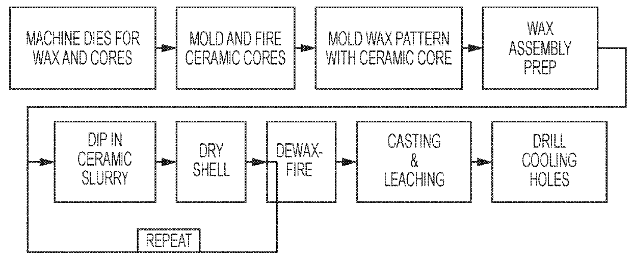
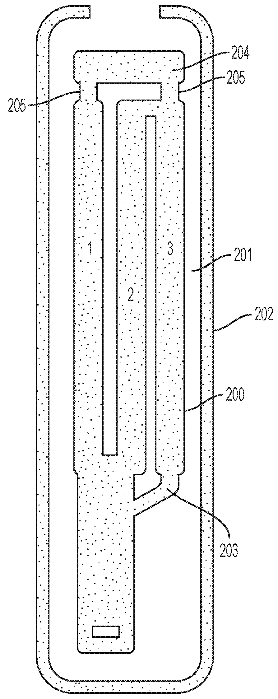
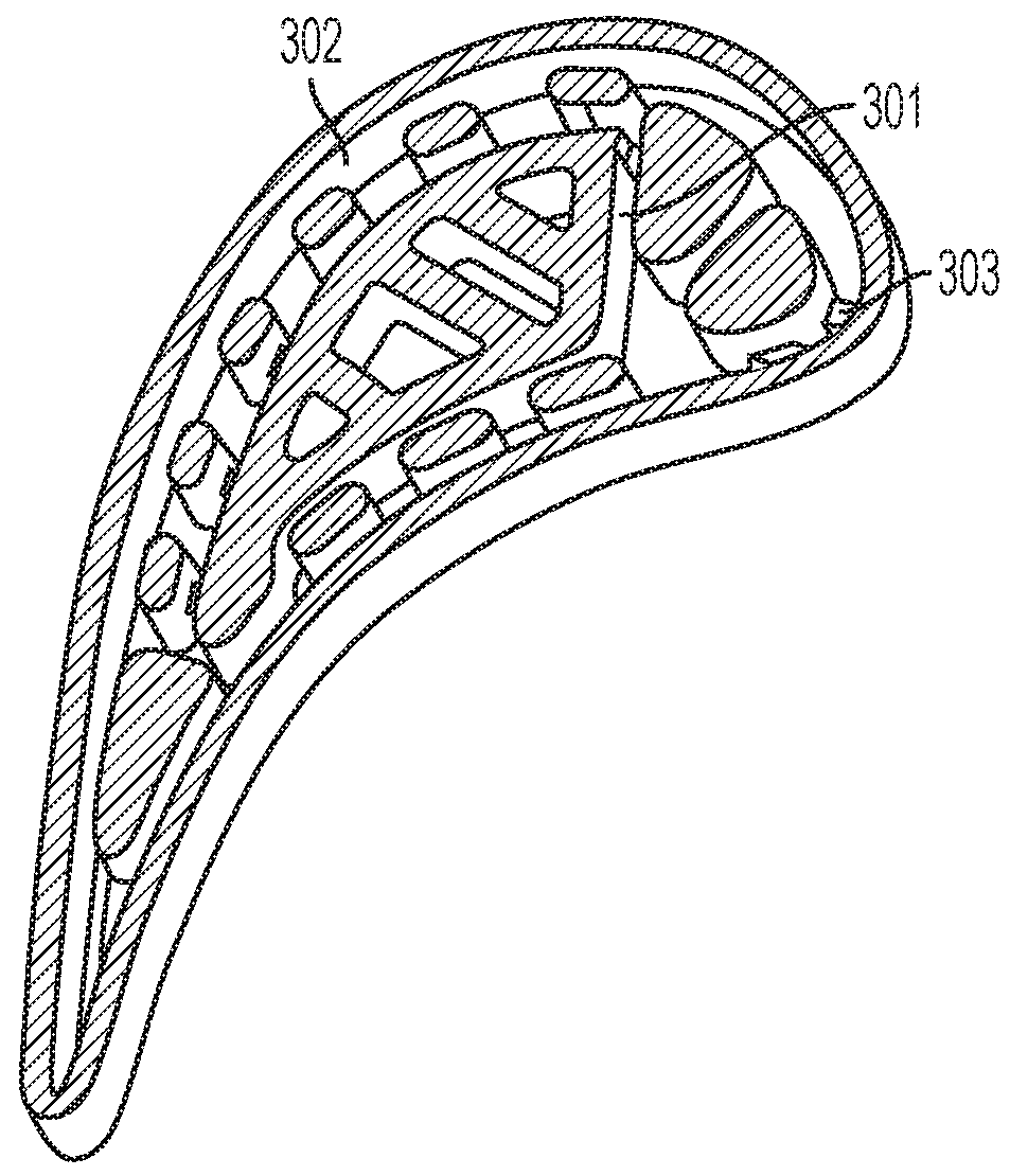
[0020]The detailed description set forth below in connection with the appended drawings is intended as a description of various configurations and is not intended to represent the only configurations in which the concepts described herein may be practiced. The detailed description includes specific details for the purpose of providing a thorough understanding of various concepts. However, it will be apparent to those skilled in the art that these concepts may be practiced without these specific details. For example, the present invention provides a preferred method for making cast metal parts, and preferably those cast metal parts used in the manufacture of jet aircraft engines. Specifically, the production of single crystal, nickel-based superalloy cast parts such as turbine blades, vanes, and shroud components can be advantageously produced in accordance with this invention. However, other cast metal components may be prepared using the techniques and integrated ceramic molds of t...


PUM

PropertyMeasurementUnit
Areaaaaaaaaaaa
Areaaaaaaaaaaa
Shapeaaaaaaaaaa

Abstract

The present disclosure generally relates to integrated core-shell investment casting molds including a main core portion, a core tip portion, and a shell portion with at least one cavity between the core portion and the shell portion. The cavity defines the shape of a cast component upon casting and removal of the ceramic mold. These molds also provide filament structures corresponding to cooling hole patterns in the surface of the turbine blade or the stator vane, which provide a leaching pathway for the core portion after metal casting. At least two ceramic tip filaments connect the core tip portion and the shell portion and eliminate the need for tip pins or a shell lock to hold the tip plenum core in place during casting. The invention also relates to core filaments that can be used to supplement the leaching pathway, for example in a core tip portion of the mold.

Description

INTRODUCTION[0001]The present disclosure generally relates to investment casting core-shell mold components and processes utilizing these components. The core-shell mold made in accordance with the present invention includes integrated ceramic filaments between the core and shell of the mold that can be utilized to form holes, i.e., effusion cooling holes, in the cast component made from these molds. The use of sufficient ceramic filaments between core and shell to both locate and provide leaching pathways for the core serpentine also enables the elimination of ball braze chutes. Ceramic filaments between the tip plenum core and the shell may also be provided to support a floating tip plenum, eliminating the need for traditional tip pins, and their subsequent closure by brazing. The integrated core-shell molds provide useful properties in casting operations, such as in the casting of superalloys used to make turbine blades and stator vanes for jet aircraft engines or power generatio...

Claims


Application Information

Patent Timeline
IPC IPC(8): B22C9/22B22D29/00B22C9/10B22C9/04B22C7/02B29C67/00B28B1/00B33Y10/00B33Y80/00
CPCB22C9/22B22D29/002B22C9/10B22C9/04B29L2031/757B29C67/0066B28B1/001B33Y10/00B33Y80/00B22C7/02B22C9/02B22C9/24B22C13/08B22D27/045F01D5/16G03F7/0037B29C64/124B29C64/135
Inventor DEINES, JAMES HERBERTPRZESLAWSKI, BRIAN DAVIDMCCARREN, MICHAEL JOHNGARAY, GREGORY TERRENCEKONITZER, DOUGLAS GERARDMARUSKO, MARK WILLARDYANG, XIPETERSON, BRIAN PATRICK
Owner GENERAL ELECTRIC CO
Why Eureka
Try Eureka