Material exhaust connection for horizontal bore

a technology of horizontal bore and exhaust connection, which is applied in the direction of earth drilling, drilling machines and methods, directional drilling, etc., can solve the problems of disruption of drilling, use of bentonite slurry, environmental hazards of certain types of drilling fluid, etc., to reduce the size of the entrained cuttings with the teeth, increase the gas flow velocity, and reduce the size of the entrained cuttings. the effect of the teeth

Active Publication Date: 2018-06-14
BARBCO
View PDF2 Cites 10 Cited by
  • Summary
  • Abstract
  • Description
  • Claims
  • Application Information

AI Technical Summary

Benefits of technology

[0014]The method may further comprise contacting the entrained cuttings with teeth provided on the auger; and reducing a size of the entrained cuttings with the teeth. The method may further comprise a step of adjusting back pressure in the first air passage and the second air passage by changing a pattern of holes in an end plate provided on the auger.
[0015]In yet another aspect, an exemplary embodiment of the present disclosure may provide a method for drilling through earthen material comprising: directing a gas through a pilot tube disposed below ground; directing the gas near a portion of a drilling head disposed below ground in operative communication with the pilot tube; directing the gas through an interior bore defined by a first casing segment; wherein the gas moving through the chamber carries spoils cut by the cutting head rearwardly through a second casing segment connected to the first casing segment. Additionally, this embodiment or another exemplary embodiment may provide directing the gas around an auger located within the first casing segment. Additionally, this embodiment or another exemplary embodiment may provide directing the gas through the interior bore of the first casing segment while the first casing segment is rotating about a longitudinal axis. This embodiment or another exemplary embodiment may provide wherein the auger is stationary and does not rotate about the longitudinal axis. Additionally, this embodiment or another exemplary embodiment may provide directing the gas around a first section of a stationary flute of the auger having a first diameter, and thereafter directing the gas around a second section of the stationary flute having a second diameter less than the first diameter, wherein the first section is associated with a forward end of the auger such that the auger is rearwardly tapered. Additionally, this embodiment or another exemplary embodiment may provide directing the gas through an aperture defined in the stationary flute of the auger. Additionally, this embodiment or another exemplary embodiment may provide directing the gas around a forward facing surface on the stationary flute of the auger. Additionally, this embodiment or another exemplary embodiment may provide directing the gas through the interior bore of the first casing segment while the first casing segment is rotating about a longitudinal axis; directing the gas to flow through a tapered portion of the first casing segment. Additionally, this embodiment or another exemplary embodiment may provide increasing a velocity of the flowing gas carrying the spoils downstream from the tapered portion of the first casing segment. Additionally, this embodiment or another exemplary embodiment may provide increasing pressure in the gas inside the first casing segment; generating a pocket of gas retained behind spoils that increases in pressure until the pocket of gas behind the spoils overcomes forces retaining the spoils inside the first casing segment; releasing the pocket of gas, in one or more burps, in response to the pocket of gas overcoming the forces that retain the spoils in the first casing segment.
[0016]In yet another aspect, an exemplary embodiment of the present disclosure may provide a method for drilling through earthen material comprising: rotating a first casing segment about a longitudinal axis disposed below ground; receiving spoils composed of cut aggregate material carried by a gas in the first casing segment; advancing the first casing segment forwardly simultaneous to rotation of the first casing segment to cut earthen material into aggregate material; and effecting rearwardly displacement of the cut aggregate material carried by the gas through the first casing segment. Additionally, this embodiment or another exemplary embodiment may provide effecting aggregate material to pass along a portion of an auger at least partially disposed within the first casing segment. Additionally, this embodiment or another exemplary embodiment may provide maintaining the auger stationary relative to the first casing segment so that the auger does not rotate about the longitudinal axis. Additionally, this embodiment or another exemplary embodiment may provide maintaining an a longitudinally aligned aperture formed in a flight of the auger in a fixed orientation relative to the longitudinal axis. Additionally, this embodiment or another exemplary embodiment may provide rotating the auger about the longitudinal axis relative to the first casing segment. Additionally, this embodiment or another exemplary embodiment may provide rotating a longitudinally aligned aperture formed in a flight of the auger about the longitudinal axis. Additionally, this embodiment or another exemplary embodiment may provide rotating the auger opposite a rotational direction of the first casing segment. Additionally, this embodiment or another exemplary embodiment may provide channeling the gas near a portion of a cutting head connected to the first casing segment such that the cutting head rotates in unison with the first casing segment; precluding the gas from flowing exterior the first casing segment; and effecting cut aggregate material to be mixed with the gas inside the first casing segment between an inner surface of the first casing segment and an outer surface of a stationary auger disposed within the first casing segment.

Problems solved by technology

The use of certain types of drilling fluids may present environmental hazards and may be prohibited by environmental laws or regulations in certain circumstances.
Although bentonite is non-toxic, the use of a bentonite slurry may be harmful to aquatic plants and fish and their eggs, as these may be smothered by the fine bentonite particles if discharged into waterways.
Other issues faced in drilling applications include that the terrain itself may cause disruptions to drilling.

Method used


Image

  • Material exhaust connection for horizontal bore
  • Material exhaust connection for horizontal bore
  • Material exhaust connection for horizontal bore

Examples


Embodiment Construction

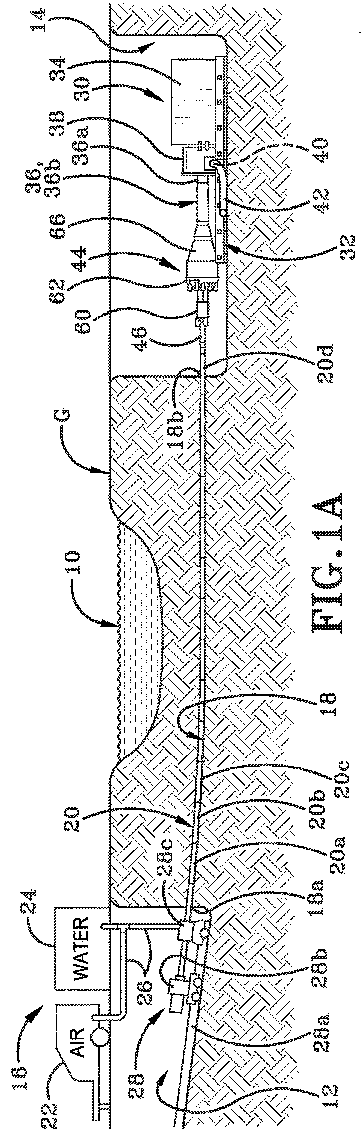
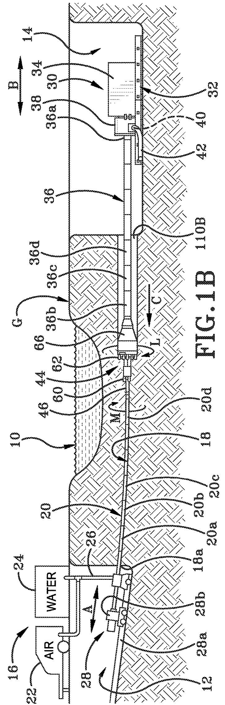
[0053]FIG. 1 shows an area of terrain or ground “G” that includes an environmental obstacle 10 under which it is necessary to drill a borehole in order to lay a length of pipe. The obstacle 10 in this particular instance is illustrated as a body of water such as a stream, a river, a pond or a lake. It will be understood, however, that obstacle 10 may represent any other type of obstacle such as roads, buildings, walls, and trees and so forth such that trenchless or horizontal directional drilling (HDD drilling) is desirable or required.

[0054]In order to conduct a drilling operation in ground “G”, a first pit 12 is dug in the ground “G” on one side of obstacle 10 and a second pit 14 is dug in ground “G” on the opposite side of obstacle 10. First pit 12 may be used to set up a control assembly 16 that may include a variety of different pieces of equipment at various times. Some of the equipment may be utilized to drill a pilot hole 18 from first pit 12 to second pit 14 and for inserti...


PUM


Abstract

An earth boring apparatus may include an earth-boring cutter head, and a casing secured to the cutter head and extending rearwardly therefrom so that the casing and cutter head are rotatable together as a unit. A casing cuttings passage may extend from adjacent the casing front end to adjacent the casing back end. An entrance opening of the casing cuttings passage, which is adjacent the cutter head, is adapted to allow cuttings to move through the entrance opening into the casing cuttings passage. In some implementations there may be a stationary auger positioned within the casing cuttings passage rearwardly from the entrance opening, such that the stationary auger does not rotate when the casing and cutter head are rotated together as a unit.

Description

CROSS REFERENCE TO RELATED APPLICATIONS[0001]This application is a continuation-in-part of U.S. application Ser. No. 15 / 634,381, filed on Jun. 27, 2017, and U.S. application Ser. No. 14 / 908,330 filed Jan. 28, 2016, which is a National Phase of PCT Application No. US2015 / 018847 filed Mar. 5, 2015, which claims priority to Provisional Application No. 61 / 948,798 filed Mar. 6, 2014, the disclosure of which is incorporated herein by reference.BACKGROUNDTechnical Field[0002]The invention relates generally to an apparatus and method for drilling generally horizontal boreholes. More particularly, the invention is directed to a cutting assembly in which pressurized air is used to facilitate removal of the spoil or cuttings from the borehole. Specifically, the invention relates to a cutting assembly having a front cutting head and a larger diameter rear cutting head. A housing extends rearwardly from the rear cutting head and connects to a casing. An annular collar on the cutting assembly sea...

Claims


Application Information

Patent Timeline
Patent Type & Authority Applications(United States)
IPC IPC(8): E21B7/04E21B7/28E21B7/20E21B7/06
CPCE21B7/046E21B7/28E21B7/201E21B7/061E21B7/20
Inventor BARBERA, ANTHONY
Owner BARBCO
Why Eureka
Try Eureka