Transverse electromagnetic horn antenna having a curved surface

a transverse electromagnetic horn and antenna technology, applied in the field of high-power microwave systems, can solve the problems of reducing aperture efficiency, reducing gain and power delivered to the target, and unsatisfactory phase variations of radiating field, so as to suppress back-lobe radiation and increase forward lobe

Active Publication Date: 2018-06-14
BAE SYST INFORMATION & ELECTRONICS SYST INTERGRATION INC
View PDF4 Cites 7 Cited by
  • Summary
  • Abstract
  • Description
  • Claims
  • Application Information

AI Technical Summary

Benefits of technology

[0004]Thus, an improved TEM horn antenna system is needed. The present disclosure addresses this need by providing

Problems solved by technology

However, in the conventional TEM horn antenna, the increase of aperture dimension for a given length of the horn may lead to undesirable phase variations of radiating field in its aperture as the wave becomes spherical.
This reduces aperture efficiency and consequently reduces the gain and the power delivered to the target.
To avoid gain reduction and power reduc

Method used


Image

  • Transverse electromagnetic horn antenna having a curved surface
  • Transverse electromagnetic horn antenna having a curved surface
  • Transverse electromagnetic horn antenna having a curved surface

Examples


Embodiment Construction

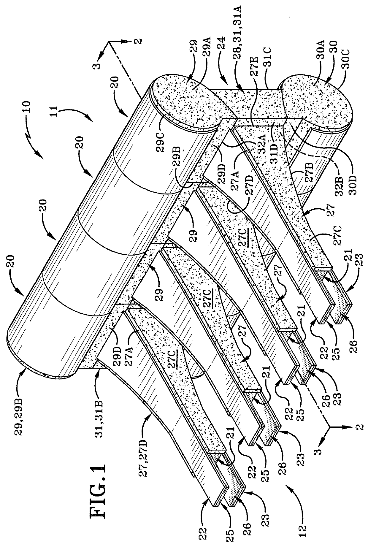
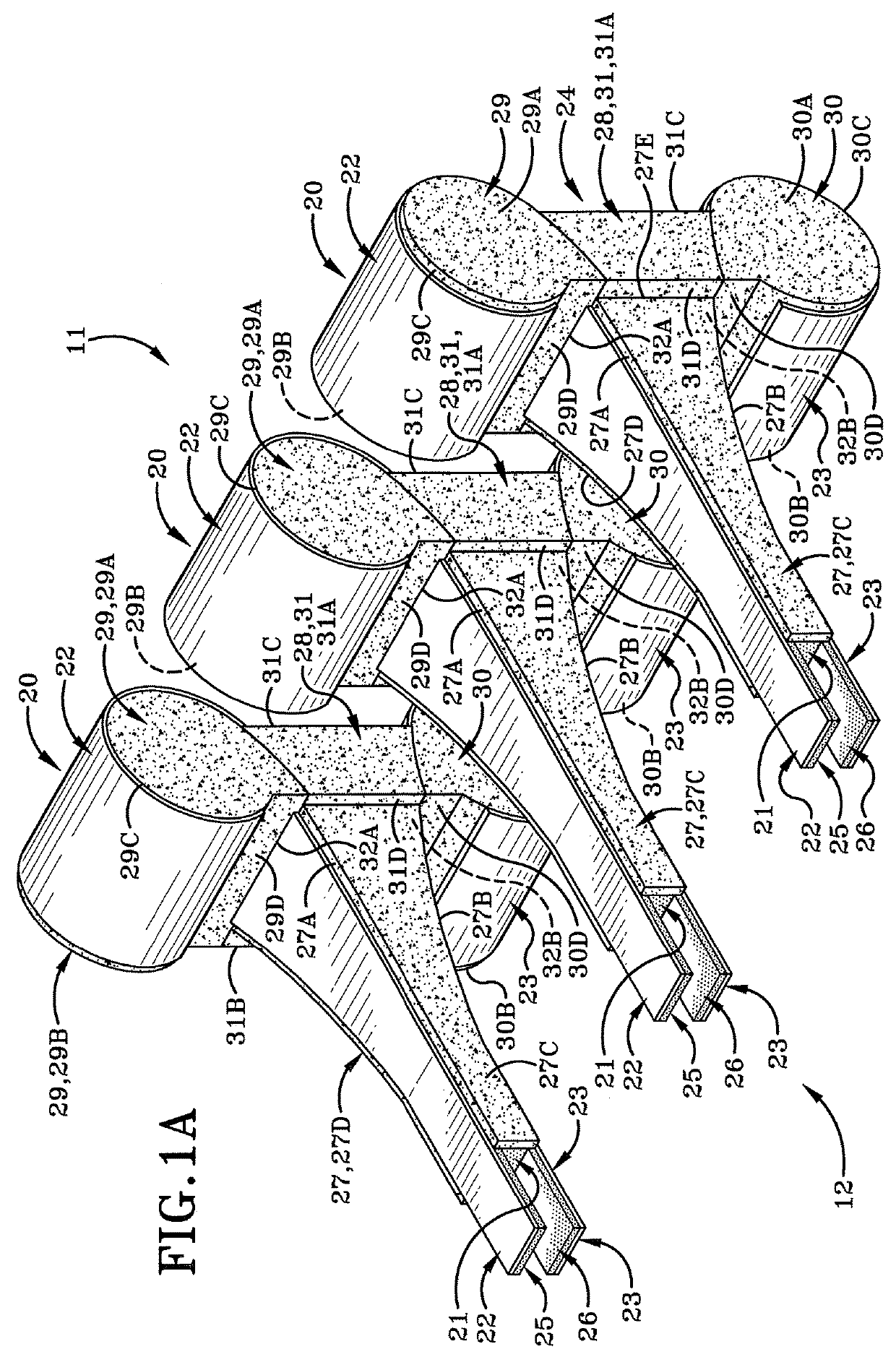
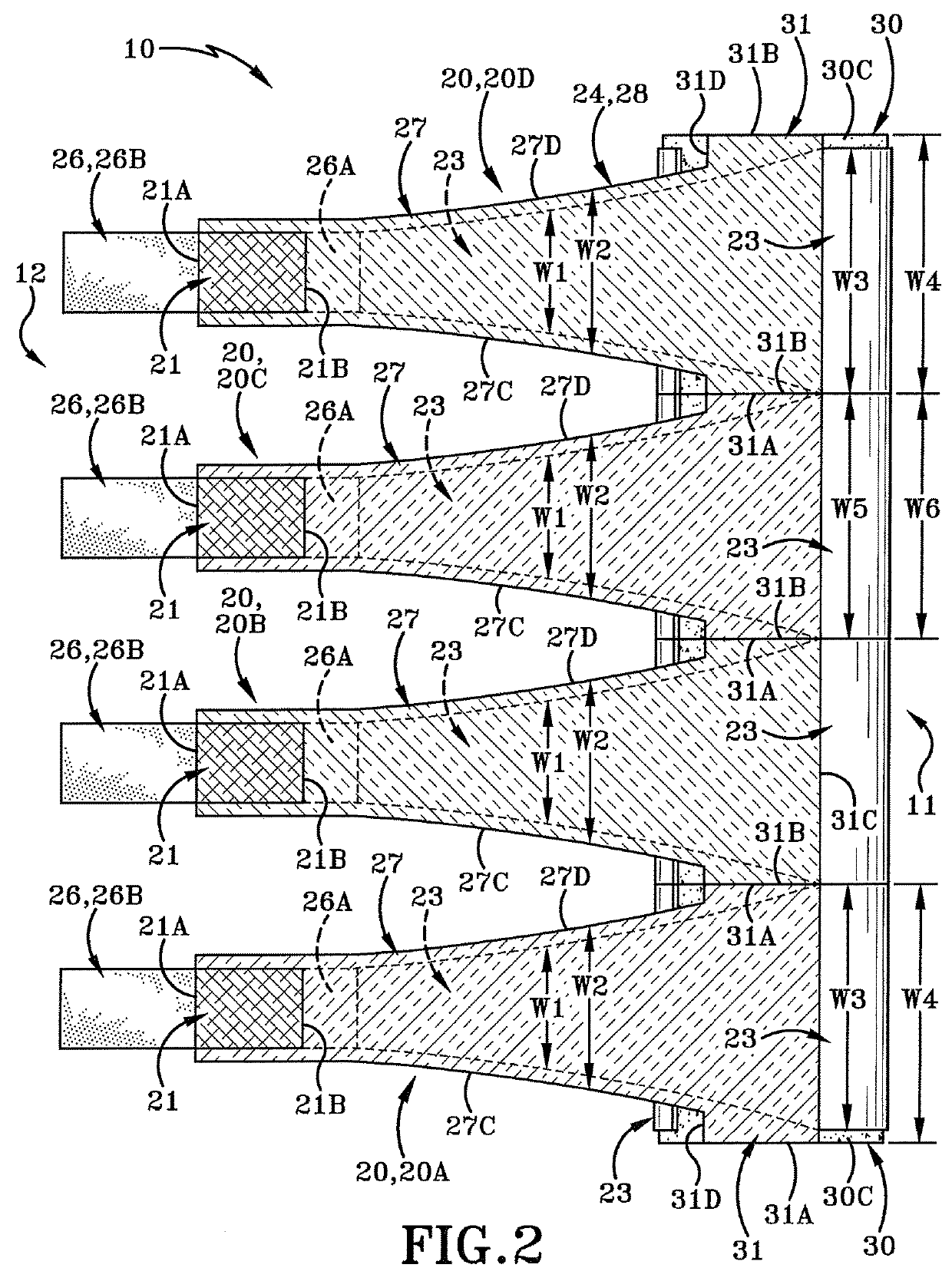
[0020]The present disclosure relates to a transverse electromagnetic (TEM) horn antenna array which can maximize the aperture efficiency without making the antenna structure too long. In order to maximize the aperture efficiency without making the antenna structure too long, in-phase aperture distortion by multi-point array type excitation is attained. The TEM horn antenna array presents as a hybrid radiating structure which is a discrete co-phased array by its feed network. Further, the TEN horn antenna array is an aperture antenna by the radiation mechanism that takes advantage of the modular nature of the TEM antenna system. In order to suppress the large back-lobe radiation issue, a curved surface section has been attached to the outside of the aperture edges.

[0021]FIG. 1 illustrates a present embodiment of a TEM horn antenna array system generally at 10. The system 10 includes a forward end 11 opposite a rear end 12. The forward end is oriented towards an incoming signal such t...


PUM


Abstract

The current disclosure is directed to a radar system. More particularly, the current disclosure relates to a fabrication of aperture-matched array of TEM horn antenna system and use of the same. Specifically, the current disclosure is directed to a compact and lightweight impulse radiating TEM array antenna system with high forward-to-back lobe ratio. Furthermore, the current TEM horn antenna system shows radiation efficiency close to 1 at the frequency bands between 150 and 250 MHz. More particularly, the current disclosure provides transverse electromagnetic (TEM) horn antenna including a curved surface extending arcuately at least 180° degrees from an antenna aperture opening defined at a signal-receiving forward end of a horn structure, wherein the curved surface is adapted to suppress large back-lobe properties.

Description

STATEMENT OF GOVERNMENT INTEREST[0001]The invention was made with government support under Contract No. W9113M-08-C-0030 awarded by the United States Department of the Army. The government has certain rights in the invention.BACKGROUNDTechnical Field[0002]Generally, the present disclosure relates to a high power microwave system. More particularly, the present disclosure relates to fabrication of aperture-matched array of TEM antenna and use of the same. Specifically, the current disclosure is directed to a compact and lightweight impulse radiating TEM array antenna with high main-to-back lobe ratio.Background Information[0003]A transverse electromagnetic (TEM) horn antenna is a parallel plate waveguide which acts as an impedance transformer. Conventional TEM horn antennas use a uniform linear or exponentially tapering profile for impedance transformation starting from a feeding point to the antenna aperture. However, in the conventional TEM horn antenna, the increase of aperture di...

Claims


Application Information

Patent Timeline
IPC IPC(8): H01Q13/02H01Q13/28
CPCH01Q13/28H01Q13/02H01Q13/085H01Q21/08
Inventor KOZYREV, ALEXANDER B.
Owner BAE SYST INFORMATION & ELECTRONICS SYST INTERGRATION INC
Why Eureka
Try Eureka