
Aircraft assembly and method

a technology for aircraft and components, applied in vehicle position/course/altitude control, process and machine control, instruments, etc., can solve the problems of aero-acoustic noise, considerable noise, particularly undesirable aero-acoustic noise, etc., to reduce impact loads, reduce the duration of aero-acoustic noise, and increase the speed of deployment

Active Publication Date: 2018-06-21
MESSIER DOWTY
View PDF10 Cites 6 Cited by
  • Summary
  • Abstract
  • Description
  • Claims
  • Application Information

AI Technical Summary

Benefits of technology

This patent describes an aircraft assembly with an automatic landing gear deployment controller that can deploy the landing gear before touchdown, keeping the aircraft in a low-noise generation state. The controller is better at deploying the gear than a human pilot, so it can be deployed later. The controller can also adjust the aircraft trim during the landing gear deployment to prevent instability when landing. The landing gear can be routinely deployed by gravity, which decreases the duration of aero-acoustic noise generated during a landing approach. The retraction linkage allows for independent movement between two joints, so the landing gear can be fully deployed even if the retraction actuator jams. Overall, this patent enables safer, more efficient, and quieter landings of aircraft.

Problems solved by technology

An aircraft can generate considerable noise during a landing approach.
A significant portion of this noise can be attributable to air flowing around the deployed landing gear.
Although the aircraft may be travelling at around 80 m / s during the landing approach, the localised airflow around a noise-inducing component or region of the landing gear may reach speeds of around 300 m / s, which can result in considerable noise.
Aero-acoustic noise is particularly undesirable because of the fact that airports are often located close to cities, or other densely populated areas.

Method used


Image

  • Aircraft assembly and method
  • Aircraft assembly and method
  • Aircraft assembly and method

Examples


Embodiment Construction

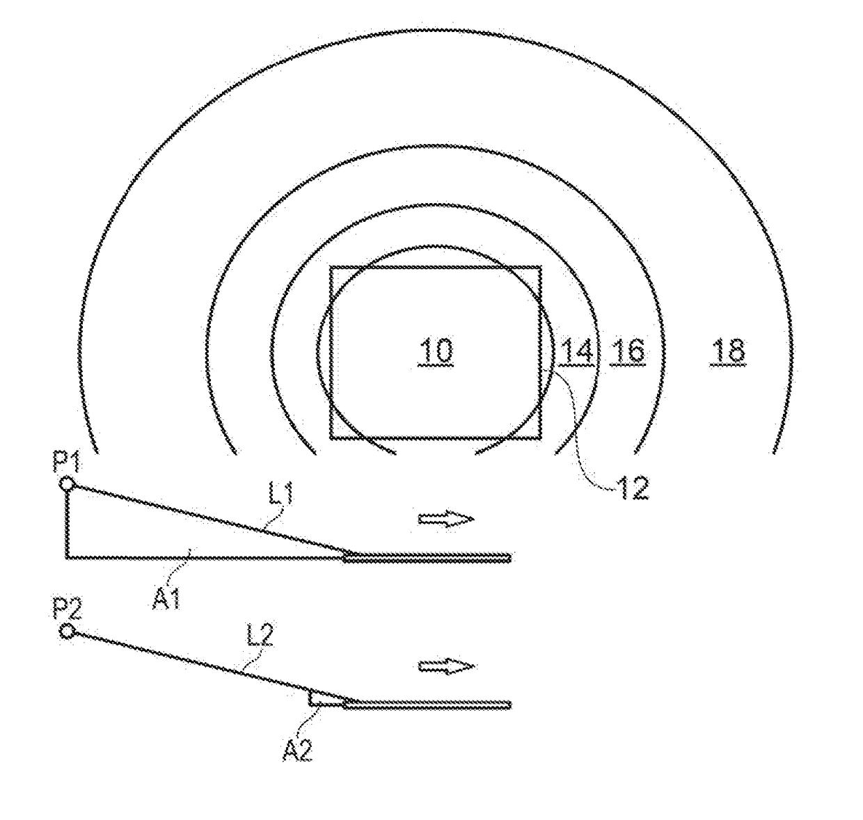
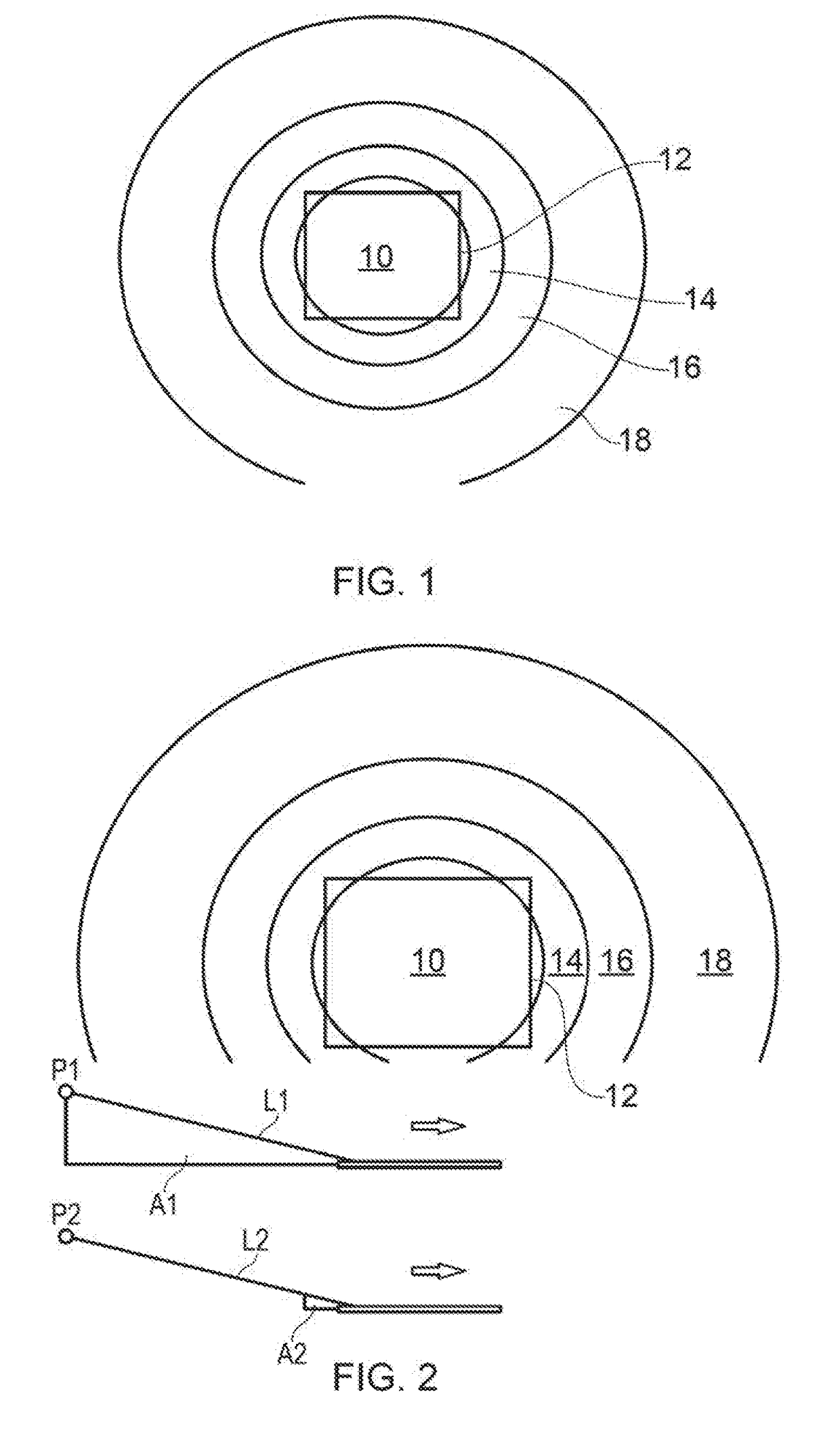
[0031]Referring to FIG. 1, an aircraft noise footprint can be considered as a geographical space surrounding an airport 10. Concentric circles define zones 12-18 of noise acceptability. A high level of noise may be accepted in zone 12, which is closest to the airport 10. The level of noise that is acceptable in the next zone out 14 can be less than the acceptable noise level in zone 12. Likewise, the level of noise that is acceptable in zone 16 may be less than that of zone 14, and so on for zone 18.

[0032]Referring to FIG. 2, in a conventional aircraft landing approach it is common for the landing gear to be deployed long before touchdown; for example, in the case of a large civil airliner, it is common for the landing gear to be deployed around 10 miles away from the runway. The angled lines L1, L2 represent a conventional aircraft glideslope path for planes P1, P2. The triangular areas A1, A2 under the lines L1, L2 represent the phase in which the landing gear are extended and the...


PUM


Abstract

An aircraft assembly having landing gear with a known deployment value, apparatus for permitting landing gear deployment, down-lock sensing apparatus, a navigation system, a landing gear control system, a flight control system, and a deployment controller. The deployment controller is configured to: calculate a touch down value using the aircraft position and speed information provided by the aircraft navigation system; command the landing gear control system to provide the deploy signal when the touch down value reaches a deployment threshold value which is greater than the landing gear deployment value; and command the flight control system to execute a landing abort sequence if the controller does not receive the down-lock signal from the landing gear sensing apparatus within a deployment value window which is greater than or equal to the known deployment value for the landing gear but less than the touch down value.

Description

[0001]This application claims the benefit of and priority to European Application EP 16205634.5, filed on Dec. 21, 2016, the contents of which are incorporated herein by reference.BACKGROUND OF THE INVENTION[0002]An aircraft can generate considerable noise during a landing approach. A significant portion of this noise can be attributable to air flowing around the deployed landing gear. Although the aircraft may be travelling at around 80 m / s during the landing approach, the localised airflow around a noise-inducing component or region of the landing gear may reach speeds of around 300 m / s, which can result in considerable noise. This type of noise can be referred to as aero-acoustic noise. Aero-acoustic noise is particularly undesirable because of the fact that airports are often located close to cities, or other densely populated areas.SUMMARY OF THE INVENTION[0003]According to a first aspect of the present invention, there is provided an aircraft assembly having:[0004]one or more ...

Claims


Application Information

Patent Timeline
Patent Type & Authority Applications(United States)
IPC IPC(8): B64C25/28B64D45/00
CPCB64C25/28B64D45/0005B64C2025/003G05D1/0676B64C25/26B64C13/16B64D45/04
Inventor SCHMIDT, ROBERT KYLE
Owner MESSIER DOWTY
Learn More